VigorIPPBX3510/3500 Series User’s Guide Version: 1.
Copyright Information Copyright Declarations Copyright 2009 All rights reserved. This publication contains information that is protected by copyright. No part may be reproduced, transmitted, transcribed, stored in a retrieval system, or translated into any language without written permission from the copyright holders. Trademarks The following trademarks are used in this document: z Microsoft is a registered trademark of Microsoft Corp.
European Community Declarations Manufacturer: Address: 303 Product: DrayTek Corp. No. 26, Fu Shing Road, HuKou Township, HsinChu Industrial Park, Hsin-Chu County, Taiwan VigorIPPBX 3510 DrayTek Corp. declares that VigorIPPBX 3510 of routers are in compliance with the following essential requirements and other relevant provisions of R&TTE Directive 1999/5/EEC.
Table of Contents Chapter 1: Preface .............................................................................................................1 1.1 Web Configuration Buttons Explanation ................................................................................. 1 1.2 LED Indicators and Connectors .............................................................................................. 2 1.2.1 For VigorIPPBX 3510 .................................................................................
5.2.1 Basics of LAN ................................................................................................................. 70 5.2.2 General Setup................................................................................................................. 72 5.2.3 Static Route .................................................................................................................... 75 5.2.4 VLAN..........................................................................................
5.11 IP PBX ............................................................................................................................... 160 5.11.1 Extension .................................................................................................................... 161 5.11.2 Line Setting................................................................................................................. 164 5.11.3 Dial Plan ............................................................................
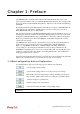
Chapter 1: Preface VigorIPPBX 3510 is an ADSL and broadband router with WAN interface. It provides policy-based load-balance, fail-over and BOD (Bandwidth on Demand), also it integrates IP layer QoS, NAT session/bandwidth management to help users control works well with large bandwidth. By adopting hardware-based VPN platform and hardware encryption of AES/DES/3DS, the router increases the performance of VPN greatly, and offers several protocols (such as IPSec/PPTP/L2TP) with up to 2 VPN tunnels.
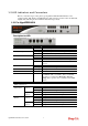
1.2 LED Indicators and Connectors Before you use the Vigor router, please get acquainted with the LED indicators and connectors first. The displays of LED indicators and connectors for the routers are different slightly. The following sections will introduce them respectively. 1.2.1 For VigorIPPBX 3510 Description for LED LED Status Explanation PWR (Power) On Off Blinking Off On Blinking On Off The router is powered on. The router is powered off. The router is powered on and running normally.
Description for Connectors Interface Factory Reset FXS FXO LAN (1-4) WAN USB PWR ON/OFF Description Restore the default settings. Usage: Turn on the router (ACT LED is blinking). Press the hole and keep for more than 5 seconds. When you see the ACT LED begins to blink rapidly than usual, release the button. Then the router will restart with the factory default configuration. Connecter for telephone set. Connecter for FXS interface of PABX. Connecters for local networked devices.
1.2.2 For VigorIPPBX 3500 Description for LED LED Status Explanation PWR (Power) On Off Blinking Off On Blinking On Off On Blinking Blinking The router is powered on. The router is powered off. The router is powered on and running normally. The router is powered off. The WAN connection is ready. It will blink while transmitting data. CDR utility has been installed and is recording. CDR utility has not been installed or is unable to record. A USB device is connected and active.
Description for Connectors Interface Factory Reset FXS FXO LAN (1-4) WAN USB PWR ON/OFF Description Restore the default settings. Usage: Turn on the router (ACT LED is blinking). Press the hole and keep for more than 5 seconds. When you see the ACT LED begins to blink rapidly than usual, release the button. Then the router will restart with the factory default configuration. Connecter for telephone set. Connecter for FXS interface of PABX. Connecters for local networked devices.
1.3 Hardware Installation Before starting to configure the router, you have to connect your devices correctly. 1. Connect the cable Modem/DSL Modem/Media Converter to WAN port of router with Connect the cable Modem/DSL Modem/Media Converter to WAN port of router with Ethernet cable (RJ-45). 2. Connect one end of an Ethernet cable (RJ-45) to one of the LAN ports of the router and the other end of the cable (RJ-45) into the Ethernet port on your computer. 3.
1.4 Printer Installation You can install a printer onto the router for sharing printing. All the PCs connected this router can print documents via the router. The example provided here is made based on Windows XP/2000. For Windows 98/SE, please visit www.draytek.com. Before using it, please follow the steps below to configure settings for connected computers (or wireless clients). 1. Connect the printer with the router through USB/parallel port. 2. Open Start->Settings-> Printer and Faxes.
3. Open File->Add a New Computer. A welcome dialog will appear. Please click Next. 4. Click Local printer attached to this computer and click Next. 5. In this dialog, choose Create a new port Type of port and use the drop down list to select Standard TCP/IP Port. Click Next.
6. In the following dialog, type 192.168.1.1 (router’s LAN IP) in the field of Printer Name or IP Address and type IP_192.168.1.1 as the port name. Then, click Next. 7. Click Standard and choose Generic Network Card. 8. Then, in the following dialog, click Finish.
9. Now, your system will ask you to choose right name of the printer that you installed onto the router. Such step can make correct driver loaded onto your PC. When you finish the selection, click Next. 10. For the final stage, you need to go back to Control Panel-> Printers and edit the property of the new printer you have added. 11. Select “LPR” on Protocol, type p1 (number 1) as Queue Name. Then click OK. Next please refer to the red rectangle for choosing the correct protocol and UPR name.
Note 1: Some printers with the fax/scanning or other additional functions are not supported. If you do not know whether your printer is supported or not, please visit www.draytek.com to find out the printer list. Open Support >FAQ; find out the link of Printer Server and click it; then click the What types of printers are compatible with Vigor router? link. Note 2: Vigor router supports printing request from computers via LAN ports but not WAN port.
This page is left blank.
Chapter 2: Configuring Basic Settings For use the router properly, it is necessary for you to change the password of web configuration for security and adjust primary basic settings. This chapter explains how to setup a password for an administrator and how to adjust basic settings for accessing Internet successfully. Be aware that only the administrator can change the router configuration. 2.
3. Now, the Main Screen will pop up. Note: The home page will change slightly in accordance with the router you have. 4. Go to System Maintenance page and choose Administrator Password. 5. Enter the login password (the default is blank) on the field of Old Password. Type New Password and Confirm Password. Then click OK to continue. 6. Now, the password has been changed. Next time, use the new password to access the Web Configurator for this router.
2.2 Quick Start Wizard If your router can be under an environment with high speed NAT, the configuration provide here can help you to deploy and use the router quickly. The first screen of Quick Start Wizard is entering login password. After typing the password, please click Next. On the next page as shown below, please select the WAN interface that you use. Choose Auto negotiation as the physical type for your router. Then click Next for next step.
On the next page as shown below, please select the appropriate Internet access type according to the information from your ISP. For example, you should select PPPoE mode if the ISP provides you PPPoE interface. Then click Next for next step. In the Quick Start Wizard, you can configure the router to access the Internet with different protocol/modes such as PPPoE, PPTP, L2TP, Static IP or DHCP. The router supports the DSL WAN interface for Internet access. 2.2.
If your ISP provides you the PPPoE connection, please select PPPoE for this router. The following page will be shown: User Name Assign a specific valid user name provided by the ISP. Password Assign a valid password provided by the ISP. Confirm Password Retype the password. Click Next for viewing summary of such connection. Click Finish. A page of Quick Start Wizard Setup OK!!! will appear. Then, the system status of this protocol will be shown.
2.2.2 PPTP/L2TP Click PPTP/L2TP as the protocol. Type in all the information that your ISP provides for this protocol. PPTP Setting --- L2TP Setting --- User Name Assign a specific valid user name provided by the ISP. Password Assign a valid password provided by the ISP. Confirm Password Retype the password.
Obtain an IP address automatically Click it to obtain the IP address automatically. Specify an IP address Click it to specify some data manually. IP Address – Type the IP address. Subnet Mask – Type the subnet mask Gateway – Type the gateway of the router. Primary DNS – Type the primary DNS address Secondary DNS – Type the secondary DNS if required. PPTP/L2TP Server – Type the IP address of the PPTP/L2TP Server. Click Next for viewing summary of such connection. Click Finish.
2.2.3 Static IP Click Static IP as the protocol. Type in all the information that your ISP provides for this protocol. WANIP Address Type the IP address. Subnet Mask Type the subnet mask. Gateway Type the gateway IP address. Primary/Secondary DNS Type in the primary IP address for the router if you want to use Static IP mode. If necessary, type in secondary IP address for necessity in the future. After finishing the settings in this page, click Next to see the following page.
Click Finish. A page of Quick Start Wizard Setup OK!!! will appear. Then, the system status of this protocol will be shown. 2.2.4 DHCP Click DHCP as the protocol. Type in all the information that your ISP provides for this protocol. Host Name Type the name of the host. MAC Some Cable service providers specify a specific MAC address for access authentication. In such cases you need to click the Specify a MAC Address and enter the MAC address in the MAC Address field.
Click Finish. A page of Quick Start Wizard Setup OK!!! will appear. Then, the system status of this protocol will be shown. 2.3 Online Status The online status shows the system status, WAN status, ADSL Information and other status related to this router within one page. If you select PPPoE as the protocol, you will find out a link of Dial PPPoE or Drop PPPoE in the Online Status web page.
Online status for PPTP Online status for Static IP 23 VigorIPPBX 3510 Series User’s Guide
Online status for DHCP Detailed explanation is shown below: Primary DNS Displays the IP address of the primary DNS. Secondary DNS Displays the IP address of the secondary DNS. LAN Status IP Address Displays the IP address of the LAN interface. TX Packets Displays the total transmitted packets at the LAN interface. RX Packets Displays the total number of received packets at the LAN interface. WAN Status Line Displays the physical connection (Ethernet) of this interface.
2.4 Saving Configuration Each time you click OK on the web page for saving the configuration, you can find messages showing the system interaction with you. Ready indicates the system is ready for you to input settings. Settings Saved means your settings are saved once you click Finish or OK button.
This page is left blank.
Chapter 3: Applications This chapter shows several scenarios for your reference to configure IP PBX for different purposes. 3.1 Versatile PSTN and VoIP Trunk z The establishment of IP registration is made through WAN port. z The remote IP -based phone with ext. 301 is registered at a SIP server. z The remote IP -based phone with ext. 201 is registered at remote site. z The analog phone or fax machine is connected to FXS module. The said VoIP No. is 888833. z The PSTN PBX is with PSTN line No.
press the extension No. 605. After getting through you can hear the dial tone, then press ext. No. 201. z The analog phone with ext. No. 602 made a call to IP phone with extension No. 301: Press extension No. 605. After getting through you will hear the dial tone, then press the ext. No. 301.
3.2 Cost-effective Extendability by Integrated Analog-telephone Adapter (for 24 Conventional Aanalog Phones) & POE-switch for IP-based phones z The establishment of IP registration is made through WAN port. z The remote IP -based phone with ext. 301 is registered at a SIP server. z The remote IP -based phone with ext. 201 is registered at remote site. z The PSTN PBX is with PSTN line No. 12345678. The remote analog phone line is No. 87654321. The remote mobile phone is with No. +49-176999661.
z The IP phone with ext. No. 201 made a call to remote analog phone (No. 87654321): Press 888835#. After getting through you will hear the dial tone, press outside line 0 and then press the PSTN number 87654321. z The analog phone with VoIP number 88829 in Shanghai made a call to the remote mobile No. (+49-176999661): Press 888842#. After getting through you will hear the dial tone, press outside line 0 and then press the mobile No. +49-176999661. z The mobile No.
Chapter 4: Other Applications 4.1 Create a LAN-to-LAN Connection Between Remote Office and Headquarter The most common case is that you may want to connect to network securely, such as the remote branch office and headquarter. According to the network structure as shown in the below illustration, you may follow the steps to create a LAN-to-LAN profile. These two networks (LANs) should NOT have the same network address. Settings in Router A in headquarter: 1.
set general settings in IPSec General Setup, such as the pre-shared key that both parties have known. 3. Go to LAN-to-LAN. Click on one index number to edit a profile. 4. Set Common Settings as shown below. You should enable both of VPN connections because any one of the parties may start the VPN connection.
5. Set Dial-Out Settings as shown below to dial to connect to Router B aggressively with the selected Dial-Out method. If an IPSec-based service is selected, you should further specify the remote peer IP Address, IKE Authentication Method and IPSec Security Method for this Dial-Out connection. If a PPP-based service is selected, you should further specify the remote peer IP Address, Username, Password, PPP Authentication and VJ Compression for this Dial-Out connection. 6.
If an IPSec-based service is selected, you may further specify the remote peer IP Address, IKE Authentication Method and IPSec Security Method for this Dial-In connection. Otherwise, it will apply the settings defined in IPSec General Setup above. If a PPP-based service is selected, you should further specify the remote peer IP Address, Username, Password, and VJ Compression for this Dial-In connection. 7.
Settings in Router B in the remote office: 1. Go to VPN and Remote Access and select Remote Access Control to enable the necessary VPN service and click OK. 2. Then, for using PPP based services, such as PPTP, L2TP, you have to set general settings in PPP General Setup. For using IPSec-based service, such as IPSec or L2TP with IPSec Policy, you have to set general settings in IPSec General Setup, such as the pre-shared key that both parties have known. 3. Go to LAN-to-LAN.
5. Set Dial-Out Settings as shown below to dial to connect to Router B aggressively with the selected Dial-Out method. If an IPSec-based service is selected, you should further specify the remote peer IP Address, IKE Authentication Method and IPSec Security Method for this Dial-Out connection. If a PPP-based service is selected, you should further specify the remote peer IP Address, Username, Password, PPP Authentication and VJ Compression for this Dial-Out connection. 6.
If a PPP-based service is selected, you should further specify the remote peer IP Address, Username, Password, and VJ Compression for this Dial-In connection. 7. At last, set the remote network IP/subnet in TCP/IP Network Settings so that Router B can direct the packets destined to the remote network to Router A via the VPN connection.
4.2 Create a Remote Dial-in User Connection Between the Teleworker and Headquarter The other common case is that you, as a teleworker, may want to connect to the enterprise network securely. According to the network structure as shown in the below illustration, you may follow the steps to create a Remote User Profile and install Smart VPN Client on the remote host. Settings in VPN Router in the enterprise office: 1.
3. Go to Remote Dial-In User. Click on one index number to edit a profile. 4. Set Dial-In settings to as shown below to allow the remote user dial-in to build VPN connection. If an IPSec-based service is selected, you may further specify the remote peer IP Address, IKE Authentication Method and IPSec Security Method for this Dial-In connection. Otherwise, it will apply the settings defined in IPSec General Setup above.
Settings in the remote host: 1. For Win98/ME, you may use "Dial-up Networking" to create the PPTP tunnel to Vigor router. For Win2000/XP, please use "Network and Dial-up connections" or “Smart VPN Client”, complimentary software to help you create PPTP, L2TP, and L2TP over IPSec tunnel. You can find it in CD-ROM in the package or go to www.draytek.com download center. Install as instructed. 2. After successful installation, for the first time user, you should click on the Step 0. Configure button.
You may further specify the method you use to get IP, the security method, and authentication method. If the Pre-Shared Key is selected, it should be consistent with the one set in VPN router. If a PPP-based service is selected, you should further specify the remote VPN server IP address, Username, Password, and encryption method. The User Name and Password should be consistent with the one set up in the VPN router.
4. Click Connect button to build connection. When the connection is successful, you will find a green light on the right down corner. 4.3 QoS Setting Example Assume a teleworker sometimes works at home and takes care of children. When working time, he would use Vigor router at home to connect to the server in the headquarter office downtown via either HTTPS or VPN to check email and access internal database. Meanwhile, children may chat on Skype in the restroom. 1.
2. Click Setup link of WAN 1. Make sure the QoS Control on the left corner is checked. And select BOTH in Direction. 3. Return to previous page. Enter the Name of Index Class 1 by clicking Edit link. Type the name “E-mail” for Class 1. 4. For this index, the user will set reserved bandwidth (e.g., 25%) for E-mail using protocol POP3 and SMTP.
5. Return to previous page. Enter the Name of Index Class 2 by clicking Edit link. In this index, the user will set reserved bandwidth for HTTPS. And click OK. 6. Click Setup link for WAN1. 7. Check Enable UDP Bandwidth Control on the bottom to prevent enormous UDP traffic of VoIP influent other application. Click OK. 8. If the worker has connected to the headquarter using host to host VPN tunnel. (Please refer to Chapter 3 VPN for detail instruction), he may set up an index for it.
Class Name of Index 3. In this index, he will set reserved bandwidth for 1 VPN tunnel. 9. Click Edit to open the following window. Check the ACT box, first. 10. Then click Edit of Local Address to set a worker’s subnet address. Click Edit of Remote Address to set headquarter’s IP address. Leave other fields and click OK.
4.4 LAN – Created by Using NAT An example of default setting and the corresponding deployment are shown below. The default Vigor router private IP address/Subnet Mask is 192.168.1.1/255.255.255.0. The built-in DHCP server is enabled so it assigns every local NATed host an IP address of 192.168.1.x starting from 192.168.1.10. You can just set the settings wrapped inside the red rectangles to fit the request of NAT usage.
To use another DHCP server in the network rather than the built-in one of Vigor Router, you have to change the settings as show below. You can just set the settings wrapped inside the red rectangles to fit the request of NAT usage. 4.5 Upgrade Firmware for Your Router Before upgrading your router firmware, you need to install the Router Tools. The file RTSxxx.exe will be asked to copy onto your computer. Remember the place of storing the execution file. 1. Go to www.draytek.com.
2. Access into Support >> Downloads. Please find out Firmware menu and click it. Search the model you have and click on it to download the newly update firmware for your router. 3. Access into Support >> Downloads. Please find out Utility menu and click it. 4. Click on the link of Router Tools to download the file. After downloading the files, please decompressed the file onto your host. 5. Double click on the router tool icon. The setup wizard will appear. 6.
7. From the Start menu, open Programs and choose Router Tools XXX >> Firmware Upgrade Utility. 8. Type in your router IP, usually 192.168.1.1. 9. Click the button to the right side of Firmware file typing box. Locate the files that you download from the company web sites. You will find out two files with different extension names, xxxx.all (keep the old custom settings) and xxxx.rst (reset all the custom settings to default settings). Choose any one of them that you need. 10. Click Send.
4.6 Request a certificate from a CA server on Windows CA Server 1. Go to Certificate Management and choose Local Certificate.
2. You can click GENERATE button to start to edit a certificate request. Enter the information in the certificate request. 3. Copy and save the X509 Local Certificate Requet as a text file and save it for later use. 4. Connect to CA server via web browser. Follow the instruction to submit the request. Below we take a Windows 2000 CA server for example. Select Request a Certificate.
Select Advanced request. Select Submit a certificate request a base64 encoded PKCS #10 file or a renewal request using a base64 encoded PKCS #7 file Import the X509 Local Certificate Requet text file. Select Router (Offline request) or IPSec (Offline request) below. Then you have done the request and the server now issues you a certificate. Select Base 64 encoded certificate and Download CA certificate. Now you should get a certificate (.cer file) and save it. 5.
and you will find the below window showing “------BEGINE CERTIFICATE------.....” 6. You may review the detail information of the certificate by clicking View button.
4.7 Request a CA Certificate and Set as Trusted on Windows CA Server 1. Use web browser connecting to the CA server that you would like to retrieve its CA certificate. Click Retrive the CA certificate or certificate recoring list.
2. In Choose file to download, click CA Certificate Current and Base 64 encoded, and Download CA certificate to save the .cer. file. 3. Back to Vigor router, go to Trusted CA Certificate. Click IMPORT button and browse the file to import the certificate (.cer file) into Vigor router. When finished, click refresh and you will find the below illustration. 4. You may review the detail information of the certificate by clicking View button.
This page is left blank.
Chapter 5: Reference Advanced Web Configuration After finished basic configuration of the router, you can access Internet with ease. For the people who want to adjust more setting for suiting his/her request, please refer to this chapter for getting detailed information about the advanced configuration of this router. As for other examples of application, please refer to chapter 4. 5.1 WAN Quick Start Wizard offers user an easy method to quick setup the connection mode for the router.
via PAP or CHAP with RADIUS authentication system. And your IP address, DNS server, and other related information will usually be assigned by your ISP. 5.1.2 Network Connection by 3G USB Modem For 3G mobile communication through Access Point is popular more and more, Vigor3510 adds the function of 3G network connection for such purpose. By connecting 3G USB Modem to the USB port of Vigor3510, it can support HSDPA/UMTS/EDGE/GPRS/GSM and the future 3G standard (HSUPA, etc).
Enable Choose Yes to invoke the settings for this WAN interface. Choose No to disable the settings for this WAN interface. Display Name Type the description for the WAN1/WAN2 interface. Physical Mode For WAN1, the physical connection is done and fixed through Ethernet port; yet the physical connection for WAN2 is done through an Ethernet port (P1) or USB port. To use 3G network connection through 3G USB Modem, choose 3G USB Modem as the physical mode in WAN2. Next, go to WAN>> Internet Access.
Load Balance Mode If you know the practical bandwidth for your WAN interface, please choose the setting of According to Line Speed. Otherwise, please choose Auto Weigh to let the router reach the best load balance. Line Speed If your choose According to Line Speed as the Load Balance Mode, please type the line speed for downloading and uploading through WAN1/WAN2. The unit is kbps.
5.1.4 Internet Access For the router supports dual WAN function, the users can set different WAN settings (for WAN1/WAN2) for Internet Access. Due to different Physical Mode for WAN1 and WAN2, the Access Mode for these two connections also varies slightly. Index It shows the WAN modes that this router supports. WAN1 is the default WAN interface for accessing into the Internet. WAN2 is the optional WAN interface for accessing into the Internet when WAN 1 is inactive for some reason.
Details Page This button will open different web page according to the access mode that you choose in WAN1 or WAN2. Details Page for PPPoE To use PPPoE as the accessing protocol of the internet, please choose Internet Access from WAN menu. Then, select PPPoE mode for WAN2. The following web page will be shown.. Enable/Disable Click Enable for activating this function. If you click Disable, this function will be closed and all the settings that you adjusted in this page will be invalid.
Assignment Method (IPCP) connect to it and request. In some case, your ISP provides service to always assign you the same IP address whenever you request. In this case, you can fill in this IP address in the Fixed IP field. Please contact your ISP before you want to use this function. WAN IP Alias - If you have multiple public IP addresses and would like to utilize them on the WAN interface, please use WAN IP Alias. You can set up to 8 public IP addresses other than the current one you are using.
Access Control Click Enable for activating this function. If you click Disable, this function will be closed and all the settings that you adjusted in this page will be invalid. Keep WAN Connection Normally, this function is designed for Dynamic IP environments because some ISPs will drop connections if there is no traffic within certain periods of time. Check Enable PING to keep alive box to activate this function.
current one you are using. Obtain an IP address automatically – Click this button to obtain the IP address automatically if you want to use Dynamic IP mode. Router Name: Type in the router name provided by ISP. Domain Name: Type in the domain name that you have assigned. Specify an IP address – Click this radio button to specify some data if you want to use Static IP mode. IP Address: Type the IP address. Subnet Mask: Type the subnet mask. Gateway IP Address: Type the gateway IP address.
Details Page for PPTP/L2TP To use PPTP/L2TP as the accessing protocol of the internet, please choose PPTP/L2TP from Internet Access menu. The following web page will be shown. PPTP/L2TP Client Mode Enable PPTP- Click this radio button to enable a PPTP client to establish a tunnel to a DSL modem on the WAN interface. Enable L2TP - Click this radio button to enable a L2TP client to establish a tunnel to a DSL modem on the WAN interface.
Settings the IP address automatically. Specify an IP address – Click this radio button to specify some data. IP Address – Type the IP address. Subnet Mask – Type the subnet mask. Details Page for PPP To use PPP (for 3G USB Modem) as the accessing protocol of the internet, please choose Internet Access from WAN menu. Then, select PPP mode for WAN2. The following web page will be shown. PPP Client Mode Click Enable to activate this mode for WAN2.
5.1.5 Load-Balance Policy This router supports the function of load balancing. It can assign traffic with protocol type, IP address for specific host, a subnet of hosts, and port range to be allocated in WAN1 or WAN2 interface. The user can assign traffic category and force it to go to dedicate network interface based on the following web page setup. Twenty policies of load-balance are supported by this router. Note: Load-Balance Policy is running only when both WAN1 and WAN2 are activated.
Move UP/Move Down Use Up or Down link to move the order of the policy. Click Index 1 to access into the following page for configuring load-balance policy. Enable Check this box to enable this policy. Protocol Use the drop-down menu to choose a proper protocol for the WAN interface. Binding WAN interface Choose the WAN interface (WAN1 or WAN2) for binding. Src IP Start Type the source IP start for the specified WAN interface. Src IP End Type the source IP end for the specified WAN interface.
5.2 LAN Local Area Network (LAN) is a group of subnets regulated and ruled by router. The design of network structure is related to what type of public IP addresses coming from your ISP. 5.2.1 Basics of LAN The most generic function of Vigor router is NAT. It creates a private subnet of your own. As mentioned previously, the router will talk to other public hosts on the Internet by using public IP address and talking to local hosts by using its private IP address.
What is Routing Information Protocol (RIP) Vigor router will exchange routing information with neighboring routers using the RIP to accomplish IP routing. This allows users to change the information of the router such as IP address and the routers will automatically inform for each other. What is Static Route When you have several subnets in your LAN, sometimes a more effective and quicker way for connection is the Static routes function rather than other method.
5.2.2 General Setup This page provides you the general settings for LAN. Click LAN to open the LAN settings page and choose General Setup. 1st IP Address Type in private IP address for connecting to a local private network (Default: 192.168.1.1). 1st Subnet Mask Type in an address code that determines the size of the network. (Default: 255.255.255.
For IP Routing Usage Click Enable to invoke this function. The default setting is Disable. 2nd IP Address Type in secondary IP address for connecting to a subnet. (Default: 192.168.2.1/ 24) 2nd Subnet Mask An address code that determines the size of the network. (Default: 255.255.255.0/ 24) 2nd DHCP Server You can configure the router to serve as a DHCP server for the 2nd subnet. Start IP Address: Enter a value of the IP address pool for the DHCP server to start with when issuing IP addresses.
2nd Subnet - Select the router to change the RIP information of the 2nd subnet with neighboring routers. DHCP Server Configuration DHCP stands for Dynamic Host Configuration Protocol. The router by factory default acts a DHCP server for your network so it automatically dispatch related IP settings to any local user configured as a DHCP client. It is highly recommended that you leave the router enabled as a DHCP server if you do not have a DHCP server for your network.
If both the Primary IP and Secondary IP Address fields are left empty, the router will assign its own IP address to local users as a DNS proxy server and maintain a DNS cache. If the IP address of a domain name is already in the DNS cache, the router will resolve the domain name immediately. Otherwise, the router forwards the DNS query packet to the external DNS server by establishing a WAN (e.g. DSL/Cable) connection. There are two common scenarios of LAN settings that stated in Chapter 4.
z create a private subnet 192.168.10.0 using an internal Router A (192.168.1.2) z create a public subnet 211.100.88.0 via an internal Router B (192.168.1.3). z have set Main Router 192.168.1.1 as the default gateway for the Router A 192.168.1.2. Before setting Static Route, user A cannot talk to user B for Router A can only forward recognized packets to its default gateway Main Router. 1. Go to LAN page and click General Setup, select 1st Subnet as the RIP Protocol Control. Then click the OK button.
3. Return to Static Route Setup page. Click on another Index Number to add another static route as show below, which regulates all packets destined to 211.100.88.0 will be forwarded to 192.168.1.3. 4. Go to Diagnostics and choose Routing Table to verify current routing table. 5.2.4 VLAN Virtual LAN function provides you a very convenient way to manage hosts by grouping them based on the physical port. You can also manage the in/out rate of each port. Go to LAN page and select VLAN.
To add or remove a VLAN, please refer to the following example. 1. If, VLAN 0 is consisted of hosts linked to P1 and P2 and VLAN 1 is consisted of hosts linked to P3 and P4. 2. After checking the box to enable VLAN function, you will check the table according to the needs as shown below. To remove VLAN, uncheck the needed box and click OK to save the results.
5.2.5 Bind IP to MAC This function is used to bind the IP and MAC address in LAN to have a strengthening control in network. When this function is enabled, all the assigned IP and MAC address binding together cannot be changed. If you modified the binding IP or MAC address, it might cause you not access into the Internet. Click LAN and click Bind IP to MAC to open the setup page. Enable Click this radio button to invoke this function.
Add It allows you to add the one you choose from the ARP table or the IP/MAC address typed in Add and Edit to the table of IP Bind List. Edit It allows you to edit and modify the selected IP address and MAC address that you create before. Remove You can remove any item listed in IP Bind List. Simply click and select the one, and click Remove. The selected item will be removed from the IP Bind List. Note: Before you select Strict Bind, you have to bind one set of IP/MAC address for one PC.
is to forward all access request with public IP address from external users to the mapping private IP address/port of the server. The port redirection can only apply to incoming traffic. To use this function, please go to NAT page and choose Port Redirection web page. The Port Redirection Table provides 20 port-mapping entries for the internal hosts. Press any number under Index to access into next page for configuring port redirection.
Enable Check this box to enable such port redirection setting. Mode Two options (Single and Range) are provided here for you to choose. To set a range for the specific service, select Range. In Range mode, if the public port (start port and end port) and the starting IP of private IP had been entered, the system will calculate and display the ending IP of private IP automatically. Service Name Enter the description of the specific network service.
conflict, such as 8080. This can be set in the System Maintenance >>Management. You then will access the admin screen of by suffixing the IP address with 8080, e.g., http://192.168.1.1:8080 instead of port 80. 5.3.2 DMZ Host As mentioned above, Port Redirection can redirect incoming TCP/UDP or other traffic on particular ports to the specific private IP address/port of host in the LAN. However, other IP protocols, for example Protocols 50 (ESP) and 51 (AH), do not travel on a fixed port.
The inherent security properties of NAT are somewhat bypassed if you set up DMZ host. We suggest you to add additional filter rules or a secondary firewall. Click DMZ Host to open the following page: If you previously have set up WAN Alias for PPPoE or Static or Dynamic IP mode, you will find them in Aux. WAN IP for your selection.
Enable Check to enable the DMZ Host function. Private IP Enter the private IP address of the DMZ host, or click Choose PC to select one. Choose PC Click this button and then a window will automatically pop up, as depicted below. The window consists of a list of private IP addresses of all hosts in your LAN network. Select one private IP address in the list to be the DMZ host. When you have selected one private IP from the above dialog, the IP address will be shown on the following screen.
Index Indicate the relative number for the particular entry that you want to offer service in a local host. You should click the appropriate index number to edit or clear the corresponding entry. Comment Specify the name for the defined network service. WAN Interface Display the WAN interface for the entry. Local IP Address Display the private IP address of the local host offering the service. Status Display the state for the corresponding entry. X or V is to represent the Inactive or Active state.
Local Computer Enter the private IP address of the local host or click Choose PC to select one. Choose PC Click this button and, subsequently, a window having a list of private IP addresses of local hosts will automatically pop up. Select the appropriate IP address of the local host in the list. Protocol Specify the transport layer protocol. It could be TCP, UDP, or ----(none) for selection. Start Port Specify the starting port number of the service offered by the local host.
5.4 Firewall 5.4.1 Basics for Firewall While the broadband users demand more bandwidth for multimedia, interactive applications, or distance learning, security has been always the most concerned. The firewall of the Vigor router helps to protect your local network against attack from unauthorized outsiders. It also restricts users in the local network from accessing the Internet. Furthermore, it can filter out specific packets that trigger the router to build an unwanted outgoing connection.
Stateful Packet Inspection (SPI) Stateful inspection is a firewall architecture that works at the network layer. Unlike legacy static packet filtering, which examines a packet based on the information in its header, stateful inspection builds up a state machine to track each connection traversing all interfaces of the firewall and makes sure they are valid. The stateful firewall of Vigor router not just examine the header information also monitor the state of the connection.
5.4.2 General Setup General Setup allows you to adjust settings of IP Filter and common options. Here you can enable or disable the Call Filter or Data Filter. Under some circumstance, your filter set can be linked to work in a serial manner. So here you assign the Start Filter Set only. Also you can configure the Log Flag settings, and Accept large incoming fragmented UDP or ICMP packets. Click Firewall and click General Setup to open the general setup page.
Please set at least one profile for anti-virus in CSM>> Web Content Filter Profile web page first. For troubleshooting needs, you can specify to record information for Web Content Filter Profile by checking the Log box. It will be sent to Syslog server. Please refer to section 5.14.5 Syslog/Mail Alert for more detailed information. Syslog For troubleshooting needs you can specify the filter log and/or CSM log here by checking the box. The log will be displayed on Draytek Syslog window.
Session timeout–Setting timeout for sessions can make the best utilization of network resources. However, Queue timeout is configured for TCP protocol only; session timeout is configured for the data flow which matched with the firewall rule. Some on-line games (for example: Half Life) will use lots of fragmented UDP packets to transfer game data.
To edit Filter Rule, click the Filter Rule index button to enter the Filter Rule setup page. Check to enable the Filter Rule Check this box to enable the filter rule. Comments Enter filter set comments/description. Maximum length is 14character long. Index(1-15) Set PCs on LAN to work at certain time interval only. You may choose up to 4 schedules out of the 15 schedules pre-defined in Applications >> Schedule setup. The default setting of this filed is blank and the function will always work.
To set the IP address manually, please choose Any Address/Single Address/Range Address/Subnet Address as the Address Type and type them in this dialog. In addition, if you want to use the IP range from defined groups or objects, please choose Group and Objects as the Address Type. From the IP Group drop down list, choose the one that you want to apply. Or use the IP Object drop down list to choose the object that you want.
want to use the service type from defined groups or objects, please choose Group and Objects as the Service Type. Protocol - Specify the protocol(s) which this filter rule will apply to. Source/Destination Port (=) – when the first and last value are the same, it indicates one port; when the first and last values are different, it indicates a range for the port and available for this service type.
record information for URL Content Filter by checking the Log box. It will be sent to Syslog server. Please refer to section 5.14.5 Syslog/Mail Alert for more detailed information. Web Content Filter Select one of the Web Content Filter profile settings (created in CSM>> Web Content Filter) for applying with this router. Please set at least one profile for anti-virus in CSM>> Web Content Filter web page first.
Window size – It determines the size of TCP protocol (0~65535). The more the value is, the better the performance will be. However, if the network is not stable, small value will be proper. Session timeout–Setting timeout for sessions can make the best utilization of network resources. However, Queue timeout is configured for TCP protocol only; session timeout is configured for the data flow which matched with the firewall rule.
Example As stated before, all the traffic will be separated and arbitrated using on of two IP filters: call filter or data filter. You may preset 12 call filters and data filters in Filter Setup and even link them in a serial manner. Each filter set is composed by 7 filter rules, which can be further defined. After that, in General Setup you may specify one set for call filter and one set for data filter to execute first.
5.4.4 DoS Defense As a sub-functionality of IP Filter/Firewall, there are 15 types of detect/ defense function in the DoS Defense setup. The DoS Defense functionality is disabled for default. Click Firewall and click DoS Defense to open the setup page. Enable Dos Defense Check the box to activate the DoS Defense Functionality. Enable SYN flood defense Check the box to activate the SYN flood defense function.
detecting this malicious exploration behavior by monitoring the port-scanning Threshold rate, the Vigor router will send out a warning. By default, the Vigor router sets the threshold as 150 packets per second. Block IP options Check the box to activate the Block IP options function. The Vigor router will ignore any IP packets with IP option field in the datagram header.
indicate the protocol type running over the upper layer. However, the protocol types greater than 100 are reserved and undefined at this time. Therefore, the router should have ability to detect and reject this kind of packets. Warning Messages We provide Syslog function for user to retrieve message from Vigor router. The user, as a Syslog Server, shall receive the report sending from Vigor router which is a Syslog Client.
5.5 Objects Settings For IPs in a range and service ports in a limited range usually will be applied in configuring router’s settings, therefore we can define them with objects and bind them with groups for using conveniently. Later, we can select that object/group that can apply it. For example, all the IPs in the same department can be defined with an IP object (a range of IP address). 5.5.1 IP Object You can set up to 192 sets of IP Objects with different conditions.
Name Type a name for this profile. Maximum 15 characters are allowed. Interface Choose a proper interface (WAN, LAN or Any). For example, the Direction setting in Edit Filter Rule will ask you specify IP or IP range for WAN or LAN or any IP address. If you choose LAN as the Interface here, and choose LAN as the direction setting in Edit Filter Rule, then all the IP addresses specified with LAN interface will be opened for you to choose in Edit Filter Rule page.
5.5.2 IP Group This page allows you to bind several IP objects into one IP group. Set to Factory Default Clear all profiles. Click the number under Index column for settings in detail. Name Type a name for this profile. Maximum 15 characters are allowed. Interface Choose WAN, LAN or Any to display all the available IP objects with the specified interface. Available IP Objects All the available IP objects with the specified interface chosen above will be shown in this box.
5.5.3 Service Type Object You can set up to 96 sets of Service Type Objects with different conditions. Set to Factory Default Clear all profiles. Click the number under Index column for settings in detail. Name Type a name for this profile. Protocol Specify the protocol(s) which this profile will apply to. Source/Destination Port Source Port and the Destination Port column are available for TCP/UDP protocol. It can be ignored for other protocols. The filter rule will filter out any port number.
(=) – when the first and last value are the same, it indicates one port; when the first and last values are different, it indicates a range for the port and available for this profile. (!=) – when the first and last value are the same, it indicates all the ports except the port defined here; when the first and last values are different, it indicates that all the ports except the range defined here are available for this service type. (>) – the port number greater than this value is available.
Name Type a name for this profile. Available Service Type Objects All the available service objects that you have added on Objects Setting>>Service Type Object will be shown in this box. Selected Service Type Objects Click >> button to add the selected IP objects in this box. 5.5.5 Keyword Object You can set 200 keyword object profiles for choosing as black /white list in CSM >>URL Web Content Filter Profile. Set to Factory Default Clear all profiles.
Name Type a name for this profile, e.g., game. Contents Type the content for such profile. For example, type gambling as Contents. When you browse the webpage, the page with gambling information will be watched out and be passed/blocked based on the configuration on Firewall settings. 5.5.6 Keyword Group This page allows you to bind several keyword objects into one group. The keyword groups set here will be chosen as black /white list in CSM >>URL Web Content Filter Profile.
Name Type a name for this group. Available Keyword Objects You can gather keyword objects from Keyword Object page within one keyword group. All the available Keyword objects that you have created will be shown in this box. Selected Keyword Objects Click this box. button to add the selected Keyword objects in 5.5.7 File Extension Object This page allows you to set eight profiles which will be applied in CSM>>URL Content Filter.
Profile Name Type a name for this profile. Type a name for such profile and check all the items of file extension that will be processed in the router. Finally, click OK to save this profile.
5.5.8 IM Object This page allows you to set 32 profiles for Instant Messenger. These profiles will be applied in CSM>>IM/P2P Filter Profile for filtering. Set to Factory Default Clear all profiles. Click the number under Profile column for configuration in details. There are several types of Instant Messenger (IM) provided here for you to choose to disallow people using. Simple check the box (es) and then click OK.
Profile Name Type a name for this profile. Type a name for such profile and check all the items that not allowed to be used in the host. Finally, click OK to save this profile.
5.5.9 P2P Object This page allows you to set 32 profiles for peer-to-peer application. These profiles will be applied in CSM>>IM/P2P Filter Profile for filtering. Set to Factory Default Clear all profiles. Click the number under Profile column for configuration in details. There are several items for P2P protocols provided here for you to choose to disallow people using. Simple check the box (es) and then click OK.
Profile Name Type a name for this profile. Type a name for such profile and check all the protocols that not allowed to be used in the host. Finally, click OK to save this profile. 5.5.10 Misc Object This page allows you to set 32 profiles for miscellaneous applications. These profiles will be applied in CSM>>IM/P2P Filter Profile for filtering. Set to Factory Default Clear all profiles. Click the number under Profile column for configuration in details.
Profile Name Type a name for this profile. Type a name for such profile and check all the protocols that not allowed to be used in the host. Finally, click OK to save this profile. 5.6 CSM CSM is an abbreviation of Content Security Management which is used to control IM/P2P usage, filter the web content and URL content to reach a goal of security management. As the popularity of all kinds of instant messenger application arises, communication cannot become much easier.
URL Content Filter To provide an appropriate cyberspace to users, Vigor router equips with URL Content Filter not only to limit illegal traffic from/to the inappropriate web sites but also prohibit other web feature where malicious code may conceal. Once a user type in or click on an URL with objectionable keywords, URL keyword blocking facility will decline the HTTP request to that web page thus can limit user’s access to the website.
5.6.1 IM/P2P Filter Profile You can define policy profiles for different policy of IM (Instant Messenger)/P2P (Peer to Peer) application. Such profile will be used in Firewall>>General Setup and Firewall>>Filter Setup pages. Set to Factory Default Clear all profiles. Click the number under Index column for settings in detail. Profile Name Type a name for the CSM profile. Each profile can contain three objects settings, IM Object, P2P Object and Misc Object.
5.6.2 URL Content Filter Profile To provide an appropriate cyberspace to users, Vigor router equips with URL Content Filter not only to limit illegal traffic from/to the inappropriate web sites but also prohibit other web feature where malicious code may conceal. Once a user type in or click on an URL with objectionable keywords, URL keyword blocking facility will decline the HTTP request to that web page thus can limit user’s access to the website.
Profile Name Type the name for such profile. Priority It determines the action that this router will apply. Both: Pass – The router will let all the packages that match with the conditions specified in URL Access Control and Web Feature below passing through. When you choose this setting, both configuration set in this page for URL Access Control and Web Feature will be inactive.
All – All the actions (Pass and Block) will be recorded in Syslog. URL Access Control Enable URL Access Control - Check the box to activate URL Access Control. Note that the priority for URL Access Control is higher than Restrict Web Feature. If the web content match the setting set in URL Access Control, the router will execute the action specified in this field and ignore the action specified under Restrict Web Feature.
keyword list, the more efficiently the Vigor router perform. Web Feature Enable Restrict Web Feature - Check this box to make the keyword being blocked or passed. Action - This setting is available only when Either : URL Access Control First or Either : Web Feature Firs is selected. Pass allows accessing into the corresponding webpage with the keywords listed on the box below. Pass - Allow accessing into the corresponding webpage with the keywords listed on the box below.
5.6.3 Web Content Filter Profile We all know that the content on the Internet just like other types of media may be inappropriate sometimes. As a responsible parent or employer, you should protect those in your trust against the hazards. With Web filtering service of the Vigor router, you can protect your business from common primary threats, such as productivity, legal liability, network and security threats. For parents, you can protect your children from viewing adult websites or chat rooms.
Action Pass - allow accessing into the corresponding webpage with the categories listed on the box below. Block - restrict accessing into the corresponding webpage with the categories listed on the box below. If the web pages do not match with the specified feature set here, it will be processed with reverse action. Log None – There is no log file will be recorded for this profile. Pass – Only the log about Pass will be recorded in Syslog. Block – Only the log about Block will be recorded in Syslog.
5.7 Bandwidth Management Below shows the menu items for Bandwidth Management. 5.7.1 Sessions Limit A PC with private IP address can access to the Internet via NAT router. The router will generate the records of NAT sessions for such connection. The P2P (Peer to Peer) applications (e.g., BitTorrent) always need many sessions for procession and also they will occupy over resources which might result in important accesses impacted.
Maximum Sessions Defines the available session number for each host in the specific range of IP addresses. If you do not set the session number in this field, the system will use the default session limit for the specific limitation you set for each index. Add Adds the specific session limitation onto the list above. Edit Allows you to edit the settings for the selected limitation. Delete Remove the selected settings existing on the limitation list.
Limitation List Display a list of specific limitations that you set on this web page. Start IP Define the start IP address for limit bandwidth. End IP Define the end IP address for limit bandwidth. TX limit Define the limitation for the speed of the upstream. If you do not set the limit in this field, the system will use the default speed for the specific limitation you set for each index. RX limit Define the limitation for the speed of the downstream.
In a QoS-enabled network, or Differentiated Service (DiffServ or DS) framework, a DS domain owner should sign a Service License Agreement (SLA) with other DS domain owners to define the service level provided toward traffic from different domains. Then each DS node in these domains will perform the priority treatment. This is called per-hop-behavior (PHB). The definition of PHB includes Expedited Forwarding (EF), Assured Forwarding (AF), and Best Effort (BE).
can be adjusted for your necessity. Yet, the last one is reserved for the packets which are not suitable for the user-defined class rules. Enable the QoS Control The factory default for this setting is checked. Please also define which traffic the QoS Control settings will apply to. IN- apply to incoming traffic only. OUT-apply to outgoing traffic only. BOTH- apply to both incoming and outgoing traffic. Check this box and click OK, then click Setup link again.
Limited_bandwidth Ratio The ratio typed here is reserved for limited bandwidth of UDP application. Online Statistics Display an online statistics for quality of service for your reference. Edit the Class Rule for QoS The first three (Class 1 to Class 3) class rules can be adjusted for your necessity. To add, edit or delete the class rule, please click the Edit link of that one. After you click the Edit link, you will see the following page. Now you can define the name for that Class.
For adding a new rule, click Add to open the following page. ACT Check this box to invoke these settings. Local Address Click the Edit button to set the local IP address (on LAN) for the rule. Remote Address Click the Edit button to set the remote IP address (on LAN/WAN) for the rule. Edit It allows you to edit source address information. Address Type – Determine the address type for the source address. For Single Address, you have to fill in Start IP address.
Edit the Service Type for Class Rule To add a new service type, edit or delete an existed service type, please click the Edit link under Service Type field. After you click the Edit link, you will see the following page.
For adding a new service type, click Add to open the following page. Service Name Type in a new service for your request. Service Type Choose the type (TCP, UDP or TCP/UDP) for the new service. Port Configuration Click Single or Range as the Type. If you select Range, you have to type in the starting port number and the end porting number on the boxes below. Port Number – Type in the starting port number and the end porting number here if you choose Range as the type.
5.8 Applications Below shows the menu items for Applications. 5.8.1 Dynamic DNS The ISP often provides you with a dynamic IP address when you connect to the Internet via your ISP. It means that the public IP address assigned to your router changes each time you access the Internet. The Dynamic DNS feature lets you assign a domain name to a dynamic WAN IP address. It allows the router to update its online WAN IP address mappings on the specified Dynamic DNS server.
3. 4. Domain Name Display the domain name that you set on the setting page of DDNS setup. Active Display if this account is active or inactive. View Log Display DDNS log status. Force Update Force the router updates its information to DDNS server. Select Index number 1 to add an account for the router. Check Enable Dynamic DNS Account, and choose correct Service Provider: dyndns.org, type the registered hostname: hostname and domain name suffix: dyndns.org in the Domain Name block.
5.8.2 Schedule The Vigor router has a built-in real time clock which can update itself manually or automatically by means of Network Time Protocols (NTP). As a result, you can not only schedule the router to dialup to the Internet at a specified time, but also restrict Internet access to certain hours so that users can connect to the Internet only during certain hours, say, business hours. The schedule is also applicable to other functions. You have to set your time before set schedule.
Enable Schedule Setup Check to enable the schedule. Start Date (yyyy-mm-dd) Specify the starting date of the schedule. Start Time (hh:mm) Specify the starting time of the schedule. Duration Time (hh:mm) Specify the duration (or period) for the schedule. Action Specify which action Call Schedule should apply during the period of the schedule. Force On -Force the connection to be always on. Force Down -Force the connection to be always down.
5.8.3 RADIUS Remote Authentication Dial-In User Service (RADIUS) is a security authentication client/server protocol that supports authentication, authorization and accounting, which is widely used by Internet service providers. It is the most common method of authenticating and authorizing dial-up and tunneled network users. The built-in RADIUS client feature enables the router to assist the remote dial-in user or a wireless station and the RADIUS server in performing mutual authentication.
5.8.4 UPnP The UPnP (Universal Plug and Play) protocol is supported to bring to network connected devices the ease of installation and configuration which is already available for directly connected PC peripherals with the existing Windows 'Plug and Play' system. For NAT routers, the major feature of UPnP on the router is “NAT Traversal”. This enables applications inside the firewall to automatically open the ports that they need to pass through a router.
The reminder as regards concern about Firewall and UPnP Can't work with Firewall Software Enabling firewall applications on your PC may cause the UPnP function not working properly. This is because these applications will block the accessing ability of some network ports. Security Considerations Activating the UPnP function on your network may incur some security threats. You should consider carefully these risks before activating the UPnP function.
5.8.5 IGMP IGMP is the abbreviation of Internet Group Management Protocol. It is a communication protocol which is mainly used for managing the membership of Internet Protocol multicast groups. For invoking IGMP Snooping function, you have to check the Enable IGMP Proxy box first for activating the IGMP proxy function. Enable IGMP Proxy Check this box to enable this function. The application of multicast will be executed through WAN port. Enable IGMP Snooping Check this box to enable this function.
5.8.6 Wake on LAN A PC client on LAN can be woken up by the router it connects. When a user wants to wake up a specified PC through the router, he/she must type correct MAC address of the specified PC on this web page of Wake on LAN of this router. In addition, such PC must have installed a network card supporting WOL function. By the way, WOL function must be set as “Enable” on the BIOS setting. Wake by Two types provide for you to wake up the binded IP.
5.9 VPN and Remote Access A Virtual Private Network (VPN) is the extension of a private network that encompasses links across shared or public networks like the Internet. In short, by VPN technology, you can send data between two computers across a shared or public network in a manner that emulates the properties of a point-to-point private link. Below shows the menu items for VPN and Remote Access. 5.9.1 Remote Access Control Enable the necessary VPN service as you need.
5.9.2 PPP General Setup This submenu only applies to PPP-related VPN connections, such as PPTP, L2TP, L2TP over IPSec. Select this option to force the router to authenticate dial-in Dial-In PPP Authentication PAP Only users with the PAP protocol. PAP or CHAP Selecting this option means the router will attempt to authenticate dial-in users with the CHAP protocol first. If the dial-in user does not support this protocol, it will fall back to use the PAP protocol for authentication.
For example, if the local private network is 192.168.1.0/255.255.255.0, you could choose 192.168.1.200 as the Start IP Address. But, you have to notice that the first two IP addresses of 192.168.1.200 and 192.168.1.201 are reserved for ISDN remote dial-in user. 5.9.3 IPSec General Setup In IPSec General Setup, there are two major parts of configuration. There are two phases of IPSec.
authentication. Pre-Shared Key- Specify a key for IKE authentication Confirm Pre-Shared Key- Retype the characters to confirm the pre-shared key. IPSec Security Method Medium - Authentication Header (AH) means data will be authenticated, but not be encrypted. By default, this option is active. High - Encapsulating Security Payload (ESP) means payload (data) will be encrypted and authenticated. You may select encryption algorithm from Data Encryption Standard (DES), Triple DES (3DES), and AES. 5.9.
Profile Name Type in a name in this file. Accept Any Peer ID Click to accept any peer regardless of its identity. Accept Subject Alternative Click to check one specific field of digital signature to accept the peer with matching value. The field can be IP Address, Name Domain, or E-mail Address. The box under the Type will appear according to the type you select and ask you to fill in corresponding setting.
5.9.5 Remote Dial-in User You can manage remote access by maintaining a table of remote user profile, so that users can be authenticated to dial-in via ISDN or build the VPN connection. You may set parameters including specified connection peer ID, connection type (ISDN Dial-In connection, VPN connection - including PPTP, IPSec Tunnel, and L2TP by itself or over IPSec) and corresponding security methods, etc. The router provides 32 access accounts for dial-in users.
Enable this account Check the box to enable this function. Idle Timeout- If the dial-in user is idle over the limitation of the timer, the router will drop this connection. By default, the Idle Timeout is set to 300 seconds. PPTP Allow the remote dial-in user to make a PPTP VPN connection through the Internet. You should set the User Name and Password of remote dial-in user below IPSec Tunnel Allow the remote dial-in user to make an IPSec VPN connection through Internet.
as the pre-shared key. Digital Signature (X.509) – Check the box of Digital Signature to invoke this function and Select one predefined Profiles set in the VPN and Remote Access >>IPSec Peer Identity. IPSec Security Method This group of fields is a must for IPSec Tunnels and L2TP with IPSec Policy when you specify the remote node. Check the Medium, DES, 3DES or AES box as the security method. Medium -Authentication Header (AH) means data will be authenticated, but not be encrypted.
inactive, respectively. Click each index to edit each profile and you will get the following page. Each LAN-to-LAN profile includes 4 subgroups. If the fields gray out, it means you may leave it untouched. The following explanations will guide you to fill all the necessary fields. For the web page is too long, we divide the page into several sections for explanation. Profile Name Specify a name for the profile of the LAN-to-LAN connection. Enable this profile Check here to activate this profile.
WAN2 First - While connecting, the router will use WAN2 as the first channel for VPN connection. If WAN2 fails, the router will use another WAN interface instead. WAN2 Only - While connecting, the router will use WAN2 as the only channel for VPN connection. Netbios Naming Packet Pass – click it to have an inquiry for data transmission between the hosts located on both sides of VPN Tunnel while connecting.
Nice to Have: Apply the IPSec policy first, if it is applicable during negotiation. Otherwise, the dial-out VPN connection becomes one pure L2TP connection. Must: Specify the IPSec policy to be definitely applied on the L2TP connection. User Name This field is applicable when you select PPTP or L2TP with or without IPSec policy above. Password This field is applicable when you select PPTP or L2TP with or without IPSec policy above.
IKE phase 1 mode -Select from Main mode and Aggressive mode. The ultimate outcome is to exchange security proposals to create a protected secure channel. Main mode is more secure than Aggressive mode since more exchanges are done in a secure channel to set up the IPSec session. However, the Aggressive mode is faster. The default value in Vigor router is Main mode.
Allowed Dial-In Type Determine the dial-in connection with different types. PPTP Allow the remote dial-in user to make a PPTP VPN connection through the Internet. You should set the User Name and Password of remote dial-in user below. IPSec Tunnel Allow the remote dial-in user to trigger an IPSec VPN connection through Internet. L2TP Allow the remote dial-in user to make a L2TP VPN connection through the Internet. You can select to use L2TP alone or with IPSec.
Password This field is applicable when you select PPTP or L2TP with or without IPSec policy above. VJ Compression VJ Compression is used for TCP/IP protocol header compression. This field is applicable when you select PPTP or L2TP with or without IPSec policy above. IKE Authentication Method This group of fields is applicable for IPSec Tunnels and L2TP with IPSec Policy when you specify the IP address of the remote node. The only exception is Digital Signature (X.
here. Herein, we provide four options: TX/RX Both, TX Only, RX Only, and Disable. From first subnet to remote network, you have to do If the remote network only allows you to dial in with single IP, please choose NAT, otherwise choose Route. Change default route to this VPN tunnel Check this box to change the default route with this VPN tunnel. Be aware that this setting is available only for WAN interface is enabled. 5.9.7 Connection Management You can find the summary table of all VPN connections.
5.10 Certificate Management A digital certificate works as an electronic ID, which is issued by a certification authority (CA). It contains information such as your name, a serial number, expiration dates etc., and the digital signature of the certificate-issuing authority so that a recipient can verify that the certificate is real. Here Vigor router support digital certificates conforming to standard X.509.
Type in all the information that the window request. Then click Generate again. Import Click this button to import a saved file as the certification information. Refresh Click this button to refresh the information listed below. View Click this button to view the detailed settings for certificate request.
5.10.2 Trusted CA Certificate Trusted CA certificate lists three sets of trusted CA certificate. To import a pre-saved trusted CA certificate, please click IMPORT to open the following window. Use Browse… to find out the saved text file. Then click Import. The one you imported will be listed on the Trusted CA Certificate window. Then click Import to use the pre-saved file. For viewing each trusted CA certificate, click View to open the certificate detail information window.
5.10.3 Certificate Backup Local certificate and Trusted CA certificate for this router can be saved within one file. Please click Backup on the following screen to save them. If you want to set encryption password for these certificates, please type characters in both fields of Encrypt password and Confirm password. Also, you can use Restore to retrieve these two settings to the router whenever you want. 5.
5.11.1 Extension The system allows you to set 100 extension numbers. Please open IP PBX>>Extension to get the following pages. There are 100 groups of extension numbers that you can configure. Please click any number under Index to set detailed configuration.
Internal Phone Extension Active Click Enable to invoke such profile. Extension Number Type the number of extension for such index. User Name Type a name for the IP PBX to execute authentication. When an IP phone connects to network, IP PBX will use such name for authentication. Authentication Check this box to make the IP PBX executing authentication while the number is dialed. Password Type a number for the IP PBX to execute authentication.
message to the users if there is a new message or the user registers on IPPBX again. Outgoing Call Use There are several outside lines (SIP accounts) for you to specify for such extension. Please check the one(s) you want. The available boxes listed here will be changed according to the FXS/FXO module inserted to VigorIPPBX 3510. Answer Mode Specify the way to process incoming phone calls. No answer after …..
5.11.2 Line Setting There are six SIP outside lines and one ISDN line provided by this IP PBX device. Users can set them respectively from SIP Trunk and PSTN Trunk. 5.11.2.1 SIP Trunk This page allows you to set profiles for six SIP outside lines at one time. Please click any number under Index to set detailed configuration.
Profile Name Assign a name for this profile for identifying. You can type similar name with the domain. For example, if the domain name is draytel.org, then you might set draytel-1 in this field. Register via If you want to make VoIP call without register personal information, please choose None and check the box to achieve the goal. Some SIP server allows user to use VoIP function without registering. Choosing Auto is recommended.
5.11.2.2 PSTN Trunk This page allows you to set profiles for PSTN outside lines at one time. Please click any number under Index to set detailed configuration. Phone Extension Active Click Enable to invoke this setting. Trunk Number The default setting is 905. Please modify it to meet the request for your PSTN environment. Manual Disconnection To disconnect the PSTN trunk, simply click the Disconnect button. The PSTN phone call will be disconnected immediately.
Off-Net PIN Code ID Type the PIN code number to make off-net call to PSTN trunk. On-Net PIN Code ID Type the PIN code number to make on-net call to PSTN trunk. Office hours answer mode Set the answering mode for such outside line in office time. You can specify it with Auto Attendant (AA), or forward it to any Extension or Group directly. Non-office hours answer mode Set the answering mode for such outside line in non-office time.
Enable Check this box to invoke this setting. Prefix Number The phone number set here is used to add, strip, or replace the OP number. Mode None - No action. Add - When you choose this mode, the OP number will be added with the prefix number for calling out through the specific VoIP interface. Strip - When you choose this mode, the OP number will be deleted by the prefix number for calling out through the specific VoIP interface.
Interface Choose the one that you want to enable the prefix number settings from the saved SIP accounts. Please set up one SIP account first to make this interface available. 5.11.3.2 Call Barring Call barring is used to block phone calls coming from the one that is not welcomed. Click any index number to display the dial plan setup page. Enable Click this to enable this entry.
Barring Type Determine the type of the VoIP phone call, URI/URL or number. It will bring out different setting options. Specific Number/Specific URI/URL This field will be changed based on the type you selected for barring Type. Please type numbers or URI/URL Interface “All” means all the phone calls will be blocked with such mechanism. Index (1-15) in Schedule Enter the index of schedule profiles to control the call barring according to the preconfigured schedules.
5.11.4.1 SIP Proxy Setting To make the IP phone to be registered in IP PBX device successfully, it is necessary for the users to configure settings in this page. SIP Local Port Set a port number as SIP local port. The default setting is 5060. SIP Proxy Realm Type SIP service domain name. In full SIP URI, such is the part after @ symbol. RTP Local Port Start/ RTP If your VoIP service provider gave you such information, please type the port number for RTP traffic.
Index You can set 10 groups for using in different conditions. Simply click the number under Index to specify detailed information. Group Name Display the name of such group. Group Extension Display the extension number of such group. Hunt List Display the members inside the group. Click any index number to display the hunt group setup page. Hunt Group Name Type suitable name for such group. Hunt Group Extension Type extension number for such group.
Sequentially - Choose such rule can make all the phones in the groups ring one by one while receiving incoming calls. Add>> Click this button to move the selected item in Available area to Chosen area. Add All Click this button to move all of the items in Available area to Chosen area. Remove<< Click this button to move the selected item in Chosen area to Available area. Remove All Click this button to clear all of the selections in Chosen area.
5.11.4.3 Voice Mail Configuration This page allows users to set actions for voices mails. Extension for checking messages The number specified here is used for the user to listen personal voice mail from IP PBX device. Attach recordings to e-mail IP PBX can send the voice mail to the specified e-mail address for the incoming call if you check this box.
5.11.4.4 Office Hours You can set ten groups of office hours including starting point, ending point on duty day(s). Office Hour Start Use the drop down menu to choose the time as the starting point. Office Hour End Use the drop down menu to choose the time as the ending point. Weekdays Check the day(s) to apply the office hour for that index. Date Specify date(s) for applying the office hour settings in holiday, for example, type 2,4 6 & 7 in the field of Date for Month 1.
5.11.4.5 Auto Attendant Wizard The first page is configured for phone calls in office hours. Click Next. The second page is configured for phone calls in non-office hours. Ring Receptionist Only the extension number selected here will ring. Plays Prompt Audio file will be played automatically. Key 2-9 Drop down menu 1 contains Ring Receptionist /Plays Prompt/Ring Hunt Group. Drop down menu 2 contains extension name (ex.
or [Prompt 1~ Prompt 10, audio files] or [Group Name (ex. Sales, RD2)]. It will be changed according to drop down menu 1. Finally, the following window will appear. 5.11.4.6 Prompt Maintenance The IP PBX system provides several audio files for users to choose for playing. Moreover, users can upload other audio files from USB storage or hard disk or others to make the IP PBX system playing. Users can record audio files and upload to router or download to PC.
Prompt 1 to prompt 10 will be used for user-defined audio files (file format must be .WAV). System Prompt file is provided by router firmware. Upload System Prompt file is provided by router firmware. To use such audio file, you have to upload it to flash memory of the router after finishing firmware update. Click this Browse button to browse and choose other audio files. Restore Click this button to save the file to the router. Next time, the audio file will be played in IP PBX system.
1. Please use DOS-BOX FTP client (Windows built-in FTP client utility) to login VigorIPPBX FTP server. 2. Press Enter to pass authentication. 3. Type put v3510_g729_userprompt.ivr. 4. Wait for a while. The message of 226 user prompts G.729 file has been uploaded successfully will appear. 5. Type quit to close FTP client. 221 Goodbye! Router will be reboot now will appear and the router will reboot. Please follow the steps below to download G.729 user Prompts to your computer: 1.
5.11.4.7 Tone Setting Tone setting is provided for fitting the telecommunication custom for the local area of the router installed. Wrong tone setting might cause inconvenience for users. To set the sound pattern of the phone set, simply choose a proper region to let the system find out the preset tone settings and caller ID type automatically. Or you can adjust tone settings manually if you choose User Defined. TOn1, TOff1, TOn2 and TOff2 mean the cadence of the tone pattern.
recommended for you to use the default settings for VoIP communication. Caller ID Type Select the caller ID type for setting Dial tone, Ringing tone, Busy tone and Congestion tone respectively. 5.11.4.8 Phone Setting This page allows user to set phone settings for FXS module. Click any index number link to open the following page for configuration. Hotline Check the box to enable it. Type in the SIP URL in the field for dialing automatically when you pick up the phone set.
Call Waiting Check this box to invoke this function. A notice sound will appear to tell the user new phone call is waiting for your response. Click hook flash to pick up the waiting phone call. FAX Mode The FAX function mode. There are several options: Transparent: FAX will be transmitted via voice channel; no fax relay and no Codec change will be involved. T.38 Relay: Using T.38 Fax Relay. This is the default value.
DTMF DTMF DTMF Mode – There are four DTMF modes for you to choose. InBand - Choose this one then the Vigor will send the DTMF tone as audio directly when you press the keypad on the phone OutBand - Choose this one then the Vigor will capture the keypad number you pressed and transform it to digital form then send to the other side; the receiver will generate the tone according to the digital form it receive.
The available boxes listed here will be changed according to the FXS/FXO module inserted to VigorIPPBX 3510. Answer Mode Specify the way to process incoming phone calls. No answer after ….. – When the incoming phone call is not picked up, it will be processed by keeping, forwarding to certain extension. Please specify the waiting time and determine the way you want to process. Busy then – When this extension number is busy, you can forward the incoming phone call to other extension number.
5.11.5 PBX Status 5.11.5.1 Call Detail Records This page displays call records of IP PBX such as failed call, successful call, no-answer call, date of the call and the duration of each call, and so on. Each page will display 50 records. Refresh Click it to reload the page. 5.11.5.2 Extension Monitor This page displays owner’s name, IP address, status and peer ID for each extension number.
Refresh Click it to reload the page. 5.12 System Maintenance For the system setup, there are several items that you have to know the way of configuration: Status, Administrator Password, Configuration Backup, Syslog, Time setup, Reboot System, Firmware Upgrade. Below shows the menu items for System Maintenance. 5.12.1 System Status The System Status provides basic network settings of Vigor router. It includes LAN and WAN interface information.
Model Name Display the model name of the router. Firmware Version Display the firmware version of the router. Build Date/Time Display the date and time of the current firmware build. LAN------MAC Address Display the MAC address of the LAN Interface. st Display the IP address of the LAN interface. st 1 Subnet Mask Display the subnet mask address of the LAN interface. DHCP Server Display the current status of DHCP server of the LAN interface.
5.12.2 TR-069 This device supports TR-069 standard. It is very convenient for an administrator to manage a TR-069 device through an Auto Configuration Server, e.g., VigorACS. ACS Server URL/Username/Password – Such data must be typed according to the ACS (Auto Configuration Server) you want to link. Please refer to Auto Configuration Server user’s manual for detailed information. CPE Client It is not necessary for you to type them. Such information is useful for Auto Configuration Server.
5.12.3 Administrator Password This page allows you to set new password. Old Password Type in the old password. The factory default setting for password is blank. New Password Type in new password in this filed. Confirm Password Type in the new password again. When you click OK, the login window will appear. Please use the new password to access into the web configurator again. 5.12.4 Configuration Backup Backup the Configuration Follow the steps below to backup your configuration. 1.
3. In Save As dialog, the default filename is config.cfg. You could give it another name by yourself. 4. Click Save button, the configuration will download automatically to your computer as a file named config.cfg. The above example is using Windows platform for demonstrating examples. The Mac or Linux platform will appear different windows, but the backup function is still available. Note: Backup for Certification must be done independently.
2. Click Browse button to choose the correct configuration file for uploading to the router. 3. Click Restore button and wait for few seconds, the following picture will tell you that the restoration procedure is successful. 5.12.5 Syslog/Mail Alert SysLog function is provided for users to monitor router. There is no bother to directly get into the Web Configurator of the router or borrow debug equipments. Enable (Syslog Access…) Check “Enable” to activate function of syslog.
Mail To Assign a mail address for sending mails out. Return-Path Assign an e-mail address of another mailbox to accept all returned messages if fatal problems occur at the recipient mailbox. The e-mail address typed here also acts as the Sender address while Vigor sends out the alert e-mails. Authentication Check this box to activate this function while using e-mail application. User Name Type the user name for authentication. Password Type the password for authentication.
5.12.6 Time and Date It allows you to specify where the time of the router should be inquired from. Current System Time Click Inquire Time to get the current time. Use Browser Time Select this option to use the browser time from the remote administrator PC host as router’s system time. Use Internet Time Select to inquire time information from Time Server on the Internet using assigned protocol. Time Protocol Select a time protocol. Server IP Address Type the IP address of the time server.
5.12.7 Management This page allows you to manage the settings for access control, access list, port setup, and SMP setup. For example, as to management access control, the port number is used to send/receive SIP message for building a session. The default value is 5060 and this must match with the peer Registrar when making VoIP calls. Allow management from the Internet Enable the checkbox to allow system administrators to login from the Internet.
Set Community Set community by typing a proper name. The default setting is private. Manager Host IP Set one host as the manager to execute SNMP function. Please type in IP address to specify certain host. Trap Community Set trap community by typing a proper name. The default setting is public. Notification Host IP Set the IP address of the host that will receive the trap community. Trap Timeout The default setting is 10 seconds. 5.12.
5.12.9 Firmware Upgrade Before upgrading your router firmware, you need to install the Router Tools. The Firmware Upgrade Utility is included in the tools. The following web page will guide you to upgrade firmware by using an example. Note that this example is running over Windows OS (Operating System). Download the newest firmware from DrayTek's web site or FTP site. The DrayTek web site is www.draytek.com (or local DrayTek's web site) and FTP site is ftp.draytek.com.
5.13 Diagnostics Diagnostic Tools provide a useful way to view or diagnose the status of your Vigor router. Below shows the menu items for Diagnostics. 5.13.1 Dial-out Trigger Click Diagnostics and click Dial-out Trigger to open the web page. The internet connection (e.g., ISDN, PPPoE, PPPoA, etc) is triggered by a package sending from the source IP address. Decoded Format It shows the source IP address (local), destination IP (remote) address, the protocol and length of the package.
5.13.2 Routing Table Click Diagnostics and click Routing Table to open the web page. Refresh Click it to reload the page. 5.13.3 ARP Cache Table Click Diagnostics and click ARP Cache Table to view the content of the ARP (Address Resolution Protocol) cache held in the router. The table shows a mapping between an Ethernet hardware address (MAC Address) and an IP address. Refresh Click it to reload the page. Clear Click it to clear the whole table.
5.13.4 DHCP Table The facility provides information on IP address assignments. This information is helpful in diagnosing network problems, such as IP address conflicts, etc. Click Diagnostics and click DHCP Table to open the web page. Index It displays the connection item number. IP Address It displays the IP address assigned by this router for specified PC. MAC Address It displays the MAC address for the specified PC that DHCP assigned IP address for it.
Peer IP:Port It indicates the destination IP address and port of remote host. Interface It displays the representing number for different interface. Refresh Click it to reload the page. 5.13.6 Ping Diagnosis Click Diagnostics and click Ping Diagnosis to pen the web page. Ping to Use the drop down list to choose the destination that you want to ping. IP Address Type in the IP address of the Host/IP that you want to ping. Run Click this button to start the ping work.
5.13.7 Data Flow Monitor This page displays the running procedure for the IP address monitored and refreshes the data in an interval of several seconds. The IP address listed here is configured in Bandwidth Management. You have to enable IP bandwidth limit and IP session limit before invoke Data Flow Monitor. If not, a notification dialog box will appear to remind you enabling it. Click Diagnostics and click Data Flow Monitor to open the web page.
Unblock – the device with the IP address will be blocked in five minutes. The remaining time will be shown on the session column. 5.13.8 Traffic Graph Click Diagnostics and click Traffic Graph to pen the web page. Choose WAN1 Bandwidth, Sessions, daily or weekly for viewing different traffic graph. Click Refresh to renew the graph at any time.
5.13.9 Trace Route Click Diagnostics and click Trace Route to open the web page. This page allows you to trace the routes from router to the host. Simply type the IP address of the host in the box and click Run. The result of route trace will be shown on the screen. Protocol Choose a protocol (ICMP or UDP) for such route. Host/IP Address It indicates the IP address of the host. Run Click this button to start route tracing work. Clear Click this link to remove the result on the window.
This page is left blank.
Chapter 6: Trouble Shooting This section will guide you to solve abnormal situations if you cannot access into the Internet after installing the router and finishing the web configuration. Please follow sections below to check your basic installation status stage by stage. z Checking if the hardware status is OK or not. z Checking if the network connection settings on your computer are OK or not. z Pinging the router from your computer. z Checking if the ISP settings are OK or not.
6.2 Checking If the Network Connection Settings on Your Computer Is OK or Not Sometimes the link failure occurs due to the wrong network connection settings. After trying the above section, if the link is stilled failed, please do the steps listed below to make sure the network connection settings is OK. For Windows The example is based on Windows XP. As to the examples for other operation systems, please refer to the similar steps or find support notes in www.draytek.com. 1.
4. Select Obtain an IP address automatically and Obtain DNS server address automatically. For MacOs 1. Double click on the current used MacOs on the desktop. 2. Open the Application folder and get into Network. 3. On the Network screen, select Using DHCP from the drop down list of Configure IPv4.
6.3 Pinging the Router from Your Computer The default gateway IP address of the router is 192.168.1.1. For some reason, you might need to use “ping” command to check the link status of the router. The most important thing is that the computer will receive a reply from 192.168.1.1. If not, please check the IP address of your computer. We suggest you setting the network connection as get IP automatically. (Please refer to the section 6.2) Please follow the steps below to ping the router correctly.
6.4 Checking If the ISP Settings are OK or Not Open Internet Access page and then check whether the ISP settings are set correctly. For PPPoE Users 1. Check if the Enable option is selected. 2. Check if Username and Password are entered with correct values that you got from your ISP.
For Static/Dynamic IP Users 1. Check if the Enable option is selected. 2. Check if Obtain an IP address automatically for Dynamic IP setting is selected. Or check if IP address, Subnet Mask and Gateway are entered with correct values for Static IP setting that you got from your ISP. For PPTP/L2TP Users 1. Check if the Enable option for PPTP Link is selected. 2. Check if PPTP Server, Username, Password and WAN IP address are set correctly (must identify with the values from your ISP).
6.5 Backing to Factory Default Setting If Necessary Sometimes, a wrong connection can be improved by returning to the default settings. Try to reset the router by software or hardware. Warning: After pressing factory default setting, you will loose all settings you did before. Make sure you have recorded all useful settings before you pressing. The password of factory default is null. Software Reset You can reset the router to factory default via Web page.
This page is left blank.
Appendix: Hardware Specifications Temperature Operating : 0°C ~ 45°C Storage : -25°C ~ 70°C Humidity 10% ~ 90% ( non-condensing ) Max.