VigorSwitch G1280 24 Ports + 4 Combo UTP/SFP Ports Web Smart Gigabit Switch User’s Guide Version: 1.0 Firmware Version: V2.1.
Copyrights © All rights reserved. This publication contains information that is protected by copyright. No part may be reproduced, transmitted, transcribed, stored in a retrieval system, or translated into any language without written permission from the copyright holders. Trademarks The following trademarks are used in this document: Microsoft is a registered trademark of Microsoft Corp. Windows, Windows 95, 98, Me, NT, 2000, XP, Vista, 7, 8, 10 and Explorer are trademarks of Microsoft Corp.
Table of Contents Part I Introduction ..............................................................................................................1 I-1 Introduction ................................................................................................................................... 2 I-1-1 Key Features ....................................................................................................................... 2 I-1-2 Specifications .................................................
II-7-1 Properties ......................................................................................................................... 38 II-7-2 IGMP Snooping ................................................................................................................ 39 II-7-2-1 IGMP Setting ..............................................................................39 II-7-2-2 IGMP Querier Setting....................................................................41 II-7-2-3 IGMP Static Group ..
V-1-1 Properties......................................................................................................................... 74 V-1-2 LLDP Port Setting ............................................................................................................ 75 V-1-3 LLDP Local Device........................................................................................................... 76 V-1-4 LLDP Remote Device.............................................................................
Part I Introduction VigorSwitch G1280 User’s Guide 1
I-1 Introduction 24 ports + 4 Combo UTP/SFP ports, Gigabit Ports Web Smart Switch is a standard switch that meets all IEEE 802.3/u/x/z Gigabit, Fast Ethernet specifications. The switch has 24 10/100/1000Mbps TP ports. It supports telnet, http, https, SSH and SNMP interface for switch management. The network administrator can logon the switch to monitor, configure and control each port’s activity. In addition, the switch implements the QoS (Quality of Service), VLAN, and Trunking.
The Power saving using the IEEE 802.3az, Energy-Efficient Ethernet to detect the client idle and cable length automatically and provides the different power. It could efficient to save the switch power and reduce the power consumption. I-1-2 Specifications The VigorSwitch G1280, a standalone off-the-shelf switch, provides the comprehensive features listed below for users to perform system network administration and efficiently and securely serve your network.
I-1-3 Packing List Before you start installing the switch, verify that the package contains the following: VigorSwitch G1280 AC Power Cord Quick Start Guide Rubber feet Rack mount kit Please notify your sales representative immediately if any of the aforementioned items is missing or damaged. I-1-4 LED Indicators and Connectors Before you use the Vigor device, please get acquainted with the LED indicators and connectors first.
(RJ 45 LNK/ACT) SFP LNK/ACT Blinking The system is sending or receiving data through the port. Off The port is disconnected or the link is failed. On (Green) The device is connected with 1000Mbps. On (Amber) The device is connected with 10/100Mpps. Blinking The system is sending or receiving data through the port. Off The port is disconnected or the link is failed.
I-2 Installation I-2-1 Typical Applications The VigorSwitch implements 24 Gigabit Ethernet TP ports with auto MDIX and four slots for the removable module supporting comprehensive fiber types of connection, including LC and BiDi-LC SFP modules. The switch is suitable for the following applications: Case 1: All switch ports are in the same local area network. Every port can access each other. (*The switch image is sample only.
Every VLAN members could not access VLAN members each other. The switch manager has to assign different names for each VLAN groups at one switch. Case 3: Port-based VLAN - 2 VLAN1 members could not access VLAN2, VLAN3 and VLAN4 members. VLAN2 members could not access VLAN1 and VLAN3 members, but they could access VLAN4 members. VLAN3 members could not access VLAN1, VLAN2 and VLAN4. VLAN4 members could not access VLAN1 and VLAN3 members, but they could access VLAN2 members.
Case 5: Desktop Installation 1. Install the switch on a level surface that can support the weight of the unit and the relevant components. 2. Plug the switch with the female end of the provided power cord and plug the male end to the power outlet. Case 6: Rack-mount Installation The switch may be standalone, or mounted in a rack. Rack mounting facilitate to an orderly installation when you are going to install series of networking devices. Procedures to Rack-mount the switch: 1.
Case 9: Office network VigorSwitch G1280 User’s Guide 9
I-2-2 Installing Network Cables Crossover or straight-through cable: All the ports on the switch support Auto-MDI/MDI-X functionality. Both straight-through or crossover cables can be used as the media to connect the switch with PCs as well as other devices like switches, hubs or router. Category 3, 4, 5 or 5e, 6 UTP/STP cable: To make a valid connection and obtain the optimal performance, an appropriate cable that corresponds to different transmitting/receiving speed is required.
I-2-5 IP Address Assignment For IP address configuration, there are three parameters needed to be filled in. They are IP address, Subnet Mask, Default Gateway and DNS. IP address: The address of the network device in the network is used for internetworking communication. Its address structure looks is shown below. It is “classful” because it is split into predefined address classes or categories. Each class has its own network range between the network identifier and host identifier in the 32 bits address.
Class D and E: Class D is a class with first 4 MSB (Most significance bit) set to 1-1-1-0 and is used for IP Multicast. See also RFC 1112. Class E is a class with first 4 MSB set to 1-1-1-1 and is used for IP broadcast. According to IANA (Internet Assigned Numbers Authority), there are three specific IP address blocks reserved and able to be used for extending internal network. We call it Private IP address and list below: Class A 10.0.0.0 --- 10.255.255.255 Class B 172.16.0.0 --- 172.31.255.
In this diagram, you can see the subnet mask with 25-bit long, 255.255.255.128, contains 126 members in the sub-netted network. Another is that the length of network prefix equals the number of the bit with 1s in that subnet mask. With this, you can easily count the number of IP addresses matched. The following table shows the result. Prefix Length No. of IP matched No.
I-3 Accessing Web Page of VigorSwitch 1. Open any browser (e.g., Firefox) and type “192.168.1.224” as URL. 2. Please type “admin/admin” as the Username/Password and click Login. 3. Now, the Main Screen will appear. Info 14 The DHCP Setting is enabled in default. Therefore, if a DHCP server presented on network connected to VigorSwitch, checking before accessing VigorSwitch is essential.
I-4 Dashboard Click Dashboard from the main menu on the left side of the main page. A web page with default selections will be displayed on the screen.
I-5 Status I-5-1 Port Bandwidth Utilization This page offers the traffic statistics inlcuding data information and data of interframe gap for each port (GE1 to GE28). In which, data of interframe gap can be displayed or hidden by choose Enable / Disable for IFG.
I-5-2 LLDP Statistics This page offers the statistics of LLDP packets (in, out and error) of each port (GE1 to GE28).
This page is left blank.
Part II Switch LAN VigorSwitch G1280 User’s Guide 19
II-1 General Setup General setup is used to configure settings for the switch network interface and offers how the switch connects to a remote server to get services. II-1-1 IP Address Use the IP Address screen to configure the switch IP address and the default gateway device. The gateway field specifies the IP address of the gateway (next hop) for outgoing traffic. The switch needs an IP address for it to be managed over the network. The factory default IP address is 192.168.1.224.
notation for example 255.255.255.0. If static mode is enabled, enter subnet mask in this field. Gateway It is available when Static is selected as Mode. Enter the IP address of the gateway in dotted decimal notation. If static mode is enabled, enter gateway address in this field. DNS Server 1 It is available when Static is selected as Mode. If static mode is enabled, enter primary DNS server address in this field. DNS Server 2 It is available when Static is selected as Mode.
Enter the IPv6 address of the router as your default IPv6 gateway to access IPv6 Internet or other IPv6 network. DHCPv6 Client Enable this feature if there is a DHCPv6 server on your network for assigning IPv6 Address, instead of using Router Advertisement. Apply Save the settings or changes to the switch. II-1-3 Management VLAN This page allows users to change the VLAN ID of management access. Management access protocols such as http, https, SNMP and etc.
II-2 Port Setting Port Setting is used to configure settings for the switch ports, trunk, Layer 2 protocols and other switch features. Available settings are explained as follows: Item Description Ports Use the drop down list to selelct one or more LAN port(s). Enable State Enable –Click it to enable the port. Disable – Click it to disable the port. Speed Port speed capabilities: Auto: Auto speed with all capabilities. Auto-10M: Auto speed with 10M ability only.
For SFP fiber module, you might need to manually configure the speed to match fiber module speed. 24 Duplex Port duplex capabilities: Auto: Auto duplex with all capabilities. Half: Auto speed with 10/100M ability only. Full: Auto speed with 10/100/1000M ability only. Flow Control A concentration of traffic on a port decreases port bandwidth and overflows buffer memory causing packet discards and frame losses.
II-3 Mirror This section provides ability to mirror packets coming in or going out on any port to a destination port. Through the packet duplication in the destination port, this feature is convinent for system administrator to monitor / understand the traffic operation. Session ID 1 to 4 can be enabled simultaneously and operate independently. Available settings are explained as follows: Item Description Session ID Select the session ID (profile 1 to 4) of mirror operation you wish to configure.
II-4 Link Aggregation LAG means Link Aggregation Group which groups some physical ports together to make a single high-bandwidth data path. Thus it can implement traffic load sharing among the member ports in a group to enhance the connection reliability. II-4-1 LAG Setting This page allows to configure Load Balance Algorithm for Link Aggregation. Available settings are explained as follows: 26 Item Description Load Balance Algorithm Select your Load balance algorithm.
II-4-2 LAG Management There are eight LAG profiles allowed to group different physical ports (GE1 to GE28). The system will assign certain port(s) as Active Member and Standby Member according to the GE selections. Available settings are explained as follows: Item Description Description Display the port description. Port Type Display the type of the LAG. Link Status Display LAG port link status. Active Member Display active member ports of the LAG.
II-4-3 LAG Port Setting This page defines port setting for each LAG profile (LAG1 to LAG8), including data speed and enabling/disabling the flow control. Available settings are explained as follows: 28 Item Description LAG Use the drop down list to selelct one or more LAG profiles. Enable Enable –Click it to enable the profile. Disable – Click it to disable the profile. Speed Port speed capabilities: Auto: Auto speed with all capabilities. Auto-10M: Auto speed with 10M ability only.
Flow Control A concentration of traffic on a port decreases port bandwidth and overflows buffer memory causing packet discards and frame losses. Flow Control is used to regulate transmission of signals to match the bandwidth of the receiving port. The switch uses IEEE802.3x flow control in full duplex mode and backpressure flow control in half duplex mode. IEEE802.
II-4-5 LACP Port Setting This section provides few detailed configuration regarding to Ports under LACP protocol. Available settings are explained as follows: 30 Item Description Ports Use the drop down list to specify LAN Port. Priority Enter a port priority number for the port. Timeout The timeout option decides how local switch of LAG connection determines connection to be lost.
II-5 VLAN Management A virtual local area network, virtual LAN or VLAN, is a group of hosts with a common set of requirements that communicate as if they were attached to the same broadcast domain, regardless of their physical location. A VLAN has the same attributes as a physical local area network (LAN), but it allows for end stations to be grouped together even if they are not located on the same network switch.
Modify - Modify the name of the selected VLAN ID. New Name - Type a name for such VLAN profile. OK - Save the settings or changes to the switch. Cancel - Close the page and return to previous page. - Delete the selected VALN ID. II-5-2 Interface Settings This page allows a user to configure interface setting related to VLAN. Available settings are explained as follows: 32 Item Description Port Select Select LAN ports to configure VLAN Settings.
the VLAN group that the tag defines. For port under Access Mode, VLAN ID provided as PVID would automatically be selected as the untagged VLAN. Accepted Type Specify the acceptable-frame-type of the specified interfaces. It’s only available with Hybrid mode. All - Accept frames regardless it's tagged with 802.1q or not. Tag Only - Accept frames only with 802.1q tagged. Untag Only - Accept frames untagged.
Disabled - Click it to disable Voice VLAN. 34 Voice VLAN Id Check the box of Enable first and then select Voice VLAN ID profile. Remark CoS/802.1p Click Enabled / Disabled to enable or disable 1p remarking. If enabled, qualified packets will be remarked by this value. Remark Value Specify the number of packets to be remarked. Specify the CoS/802.1p number you wish ingress VoIP packets be tagged with, so that QoS can prioritize it correctly. Aging Time Select value of aging time (30~65536 min).
II-5-3-2 Telephony OUI Setting This page allows a user to add, edit or delete OUI MAC addresses. Default has 8 pre-defined OUI MAC. Available settings are explained as follows: Item Description OUI Address Type OUI address. Description Enter a description of the specified MAC address to the voice VLAN OUI table. Add Click it to create a new voice OUI based on the settings configured above. Edit Click Edit for one entry to modify OUI setting for voice VLAN.
II-5-3-3 Port Setting This page allows a user to specify LAN port(s) as Voice LAN port. Available settings are explained as follows: 36 Item Description Port Use the drop down list to specify one or more LAN ports. State Enabled – Click it to enable the port settings for Voice LAN. Disabled – Click it to disable the port settings for Voice LAN. Cos Mode If Remark CoS/802.1p is enabled in Voice VLAN>>Properties, settings in this page shall be applied. Otherwise, this option will not take effect.
II-6 EEE This page allows a user to enable or disable port EEE (Energy Efficient Ethernet) function. Available settings are explained as follows: Item Description Port Select one or multiple ports to configure (GE1 to GE28). Enable Enable –Click it to enable the EEE function. Disable - Click it to disable the EEE function. Apply Save the settings or changes to the switch.
II-7 Multicast IP multicast is a technique for one-to-many communication over an IP infrastructure in a network. To avoid the incoming data broadcasting to all GE ports, multicast is useful to transfer the data/message to specified GE ports for IGMP snooping. When VigorSwitch receives a message “subscribed” by the client, it must decide to transfer the data to specified GE ports according to the location of the client (subscribed member).
II-7-2 IGMP Snooping IGMP snooping is the process of listening to Internet Group Management Protocol (IGMP) network traffic. The feature allows a network switch to listen in on the IGMP conversation between hosts and routers. By listening to these conversations the switch maintains a map of which links need which IP multicast streams. Multicasts may be filtered from the links which do not need them and thus controls which ports receive specific multicast traffic.
IGMP Snooping State –Choose Enable to enable IGMP snooping function. Router Ports Auto Learn – Set the enabling status of IGMP router port learning. Choose Enable to learn router port by IGMP query. Query Robustness – Set a number which allows tuning for the expected packet loss on a subnet. Query Interval – Set the interval of querier send general query. Query Response Interval – It specifies the maximum allowed time before sending a responding report in units of 1/10 second.
II-7-2-2 IGMP Querier Setting This page allows a user to configure querier settings on specific VLAN of IGMP Snooping. Available settings are explained as follows: Item Description VLAN ID Use the drop down list to specify a VLAN profile as IGMP Snooping querier. Querier State Enable – Click Enable to set the enabling status of IGMP Querier on the chosen VLAN profile. Disable – Click it to disable the function. Querier Version Set the query version of IGMP Querier Election on the chosen VLANs.
II-7-2-3 IGMP Static Group The IGMP static group is allowed to assign a VLAN/port as a specific IPv4 multicast member. Every IPv4 multicast stream that belongs to the specified group IP address will be forwarded to the specified port/VLAN member. Available settings are explained as follows: 42 Item Description VLAN ID Use the drop down list to specify a VLAN profile as IGMP Static Group. Group IP Address Specify the IPv4 multicast address you wish to assign for the static group (defined in VLAN ID).
II-7-2-4 IGMP Group Table This page shows currently known and dynamically learned by IGMP snooping or shows the assigned IPv4 multicast address group in operation. Available settings are explained as follows: Item Description VLAN ID Display the VLAN of this multicast group belongs to. Group IP Address Display the multicast address of this multicast group. Member Ports Display the port(s) where subscribing member of this multicast group belongs to.
II-7-2-5 IGMP Router Table This page shows the IGMP querier router known to this switch. Available settings are explained as follows: 44 Item Description VLAN ID Display the VLAN profile that the IGMP querier belongs to. Port Display the uplink ports where querier router exists. Expire Time (sec.) Display the time before querier is considered no longer existed.
II-8 Jumbo Frame This page allows a user to configure switch port jumbo frame settings. Available settings are explained as follows: Item Description Jumbo Frame (Bytes) Enter Jumbo frame size. The valid range is 1526 bytes – 9216 bytes. Apply Save the settings or changes to the switch.
II-9 STP The Spanning Tree Protocol (STP) is a network protocol that ensures a loop-free topology for any bridged Ethernet local area network. Bridge Protocol Data Units (BPDUs) are frames that contain information about the Spanning Tree Protocol (STP). Switches send BPDUs using a unique MAC address from its origin port and a multicast address as destination MAC (01:80:C2:00:00:00, or 01:00:0C:CC:CC:CD for Per VLAN Spanning Tree).
range: 1~200,000,000. Short - Specifies that the default port path costs are within the range: 1~65,535. Apply Save the settings or changes to the switch. II-9-2 Port Setting This page allows the user to configure and display STP port settings. Available settings are explained as follows: Item Description Ports Use the drop down to specify the interface ID or the list of interface IDs. Path Cost (0=Auto) Path cost is the cost of transmitting a frame on to a LAN through that port.
Apply Save the settings or changes to the switch. After clicking it, the settings configured above will be shown on the table below. Admin Enable Enable – Such port is managed by VigorSwitch. Edit Click it to modify the settings for the selected GE port. II-9-3 Bridge Setting This page allows you to configure required information to negotiate with other VigorSwitch for determining the bridge switch.
Max Age Specify the time interval in seconds for a switch to wait the configuration messages, without attempting to redefine its own configuration. Tx Hold Count Specify the tx-hold-count used to limit the maximum numbers of packets transmission per second. The valid range is from 1 to 10. Hello Time Specify the STP hello time in second to broadcast its hello message to other bridge by Designated Ports. Its valid range is from 1 to 10 seconds. Apply Save the settings or changes to the switch.
“Alternative”, and “Backup”. Port State Display current port state on the specified port. The possible values will be: “Disabled”, “Discarding”, “Learning”, and “Forwarding”. Edit Click it to modify the settings for the selected GE port / LAG port. II-9-5 Statistics This page displays STP statistics. Available settings are explained as follows: 50 Item Description Port Display the port number (GE / LAG). Configure BPDUs Rx. Display the counts of the received CONFIG BPDU. TCN BPDUs Rx.
II-10 MAC Address Table This section allows user to view the dynamic MAC address entries in the MAC table, change related setting, and assign MAC address into MAC table. II-10-1 Static MAC Setting This section allows user to manually assign MAC address into MAC table. The configuration result will be displayed on the table listed on the lower side of this web page. Available settings are explained as follows: Item Description MAC Address Enter the MAC address that will be forwarded.
II-10-2 Dynamic Address Setting This page allows a user to configure aging time for dynamic MAC address. Available settings are explained as follows: Item Description Aging Time Enter the Dynamic MAC address aging out value (5-32767 seconds). Apply Save the settings or changes to the switch. II-10-3 Dynamic Learned This page displays the MAC address and port number automatically learned by VigorSwitch.
Available settings are explained as follows: Item Description MAC Address Display the MAC address that will be forwarded. VLAN Display the VLAN group to which the MAC address belongs. Type Display whether the MAC address is Dynamic (learned by the Switch) or Static Unicast (manually entered in the Static MAC Forwarding screen). Port Display the port to which this MAC address belongs. Add to Static Click this button to add any port into the static MAC table.
This page is left blank.
Part III Security VigorSwitch P1280 User’s Guide 55
III-1 Storm Control Storm Control helps to suppress possible broadcast, unknown multicast or unknown unicast storm by applying a rate limit on those packets. III-1-1 Properties This page allows a user to configure general settings for Storm Control. Available settings are explained as follows: 56 Item Description Storm Control Mode Select the mode of storm control. Packet/sec – Storm control rate will be calculated by packet-based. Kbits/sec - Storm control rate will be calculated by octet-based.
III-1-2 Port Setting This page is used to configure port settings for Storm Control. The configuration result for each port will be displayed on the table listed on the lower side of this web page. Available settings are explained as follows: Item Description Ports Use the drop down list to select the port profile (GE1 to GE28) or profiles. Storm Control Disable – Disable the storm control configuration for the selected port profile.
III-2 DoS A Denial of Service (DoS) attack is a hacker attempt to make a device unavailable to its users. DoS attacks saturate the device with external communication requests, so that it cannot respond to legitimate traffic. These attacks usually lead to a device CPU overload. The DoS protection feature is a set of predefined rules that protect the network from malicious attacks. The DoS Security Suite Setting enables activating the security suite.
Enabled - Enable the item function. Ping of Death Avoid ping of death attack. Ping packets that length are larger than 65535 bytes. Disabled – Disable the item function. Enabled - Enable the item function. IPv6 Min Fragments Check the minimum size of IPv6 fragments, and drop the packets smaller than the minimum size. The valid range is from 0 to 65535 bytes, and default value is 1240 bytes. Disabled – Disable the item function. Enabled - Enable the item function.
Enabled - Enable the item function. TCP Fragment (Offset=1) Drop the fragmented ICMP packets. Disabled – Disable the item function. Enabled - Enable the item function. Apply Save the settings or changes to the switch. III-2-2 DoS Port Setting This page allows a user to configure and display the state of DoS protection for interfaces. The configuration result for each port will be displayed on the table listed on the lower side of this web page.
Part IV QoS Configuration VigorSwitch P1280 User’s Guide 61
IV-1 General QoS (Quality of Service) functions to provide different quality of service for various network applications and requirements and optimize the bandwidth resource distribution so as to provide a network service experience of a better quality. IV-1-1 Properties IV-1-1-1 QoS General Setting This page is used to specify Ingress Trust Mode for basic QoS mode. Available settings are explained as follows: 62 Item Description QoS Mode Disable –Disable the function of QoS mode.
IV-1-1-2 Trust Ports This page is used to enable the trust mode of basic QoS on each port. Port that is trust disabled will be sent with lowest priority queue. The configuration result for each port will be displayed on the table listed on the lower side of this web page. Available settings are explained as follows: Item Description Ports Use the drop down list to select the port profile (GE1 to GE28) or profiles. Trust Click Enable to make traffic follow the trust mode in general setting.
IV-1-2 Port Settings This page is used to configure port settings for QoS. The configuration result for each port will be displayed on the table listed on the lower side of this web page. Available settings are explained as follows: Item Description Ports Use the drop down list to select the port profile (GE1 to GE28) or profiles. Ingress Default CoS Specify the default CoS priority value for those ingress frames without given trust QoS tag (802.1q/DSCP/IP Precedence, depending on configuration).
VigorSwitch P1280 User’s Guide 65
IV-1-3 Queue Settings VigorSwitch supports multiple queues for each interface. The higher numbered queue represents the higher priority. The following lists the types of supported priority queue: Strict Priority (SP) - Egress traffic from the higher priority queue will be transmitted first, lower priority queue shall wait until all traffic in SP queue is transmitted. Weighted Round Robin (WRR) - The number of packets sent from the queue is proportional to the weight of the queue.
IV-1-4 CoS Mapping This section allows user to configure how ingress frames with CoS/802.1p tag map to QoS queues, and QoS queues to CoS/802.1p on egress frames. Actual effectiveness is based on how QoS is configured in previous QoS section. This page provides settings for user to configure mapping only. Available settings are explained as follows: Item Description CoS to Queue Mapping (for Ingress) – Settings for incoming packets. Class of Service Display the class of service value (0 to 7).
IV-1-5 DSCP Mapping This section allows user to configure how ingress packets with DSCP tag map to QoS queues, and QoS queues to DSCP on egress packets. Actual effectiveness is based on how QoS is configured in previous QoS section. This page provides settings for user to configure mapping only. Available settings are explained as follows: Item Description DSCP to Queue Mapping (for Ingress) – Settings for the incoming packets. DSCP Display the DSCP value (0 to 63).
IV-1-6 IP Precedence Mapping This section allows user to configure how ingress packets with IP Precedence tag map to QoS queues, and QoS queues to IP Precedence on egress packets. Actual effectiveness is based on how QoS is configured in previous QoS section. This page provides settings for user to configure mapping only. Available settings are explained as follows: Item Description IP Precedence to Queue Mapping (for Ingress) - Settings for the incoming packets..
IV-2 Bandwidth Use the bandwidth setting pages to define values that determine how much traffic the switch can receive and send on specific port or queue. IV-2-1 Ingress Rate Limit This page allows a user to configure ingress port rate limit. The ingress rate limit is the number of bits per second that can be received from the ingress interface. Excess bandwidth above this limit is discarded. The configuration result for each port will be displayed on the table listed on the lower side of this web page.
IV-2-2 Egress Shaping Rate This page allows a user to configure egress port rate limit. The egress rate limit is the number of bits per second that can be received from the egress interface. Excess bandwidth above this limit is discarded. Available settings are explained as follows: Item Description Egress Shapping Rate Ports Use the drop down list to select the port profile (GE1 to GE28) or profiles. State Disable – Disable egress bandwidth control. Enable - Enable egress bandwidth control.
IV-2-3 Egress Shaping Per Queue This page allows user to configure the maximum egress bandwidth not only by port but also by specific QoS queues. The configuration result for each port will be displayed on the table listed on the lower side of this web page. Available settings are explained as follows: Item Description Egress Shapping Per Queue 72 Port Use the drop down list to select the port profile (GE1 to GE28) or profiles.
Part V System Maintenance VigorSwitch G1280 User’s Guide 73
V-1 LLDP LLDP is a one-way protocol; there are no request/response sequences. Information is advertised by stations implementing the transmit function, and is received and processed by stations implementing the receive function. The LLDP category contains LLDP and LLDP-MED pages. V-1-1 Properties This page allows a user to set general settings for LLDP. Available settings are explained as follows: 74 Item Description LLDP State Enable – Enable LLDP protocol on this switch.
V-1-2 LLDP Port Setting This page allows a user to select specified port or all ports to configure LLDP state. Available settings are explained as follows: Item Description Ports Use the drop down list to select the port (GE1 to GE28) or ports for device check. State Disable – Disable the transmission of LLDP PDUs. TX&RX – Transmit and receive LLDP PDUs both. TX Only – Transmit LLDP PDUs only. RX Only - Receive LLDP PDUs only.
V-1-3 LLDP Local Device This page displays information for LLDP Local Device. Available settings are explained as follows: 76 Item Description Device Summary Display a summary of the LLDP information for this switch. Chassis ID Subtype - Display the type of chassis ID, such as the MAC address. Chassis ID - Display Identifier of chassis. Where the chassis ID subtype is a MAC address, the MAC address of the switch is displayed. System Name - Display model name of switch.
V-1-4 LLDP Remote Device This page is used to view the information sent from neighboring devices by LLDP protocol. Available settings are explained as follows: Item Description Local Port Display the number of the local port to which the neighbor is connected. Chassis ID Subtype Display the type of chassis ID (for example, MAC address). Chassis ID Display the identifier of the 802 LAN neighboring device’s chassis. Port ID Subtype Display the type of port identifier.
V-1-5 LLDP Overloading This page allows user to review current size, overall size of LLDP packet and whether it is to exceed maximum allowed size of single LLDP packet. Available settings are explained as follows: 78 Item Description Port Display the name of the port. Total(Bytes) Display the total number of bytes of LLDP information in each packet. Left to Send(Bytes) Display the total number of available bytes left for additional LLDP information in each packet.
V-2 SNMP Simple Network Management Protocol (SNMP) is an "Internet-standard protocol for managing devices on IP networks". Devices that typically support SNMP include routers, switches, servers, workstations, printers, modem racks and more. SNMP is used mostly in network management systems to monitor network-attached devices for conditions that warrant administrative attention. SNMP is a component of the Internet Protocol Suite as defined by the Internet Engineering Task Force (IETF).
VI-2-1 Properties This page allows a user to enable the function of SNMP for VigorSwitch. Available settings are explained as follows: 80 Item Description State Enable – Enable the function of SNMP. Disable – Disable the function of SNMP. Apply Save the settings or changes to the switch.
V-2-2 SNMP Community This page allows a user to add/remove multiple communities of SNMP. Available settings are explained as follows: Item Description Community Name Enter a name as community name. The maximum length of the text is limited to 23 characters. Access Right Read Only – It allows unidirectional access to node-specific information. Read & Write - It allows bidirectional access to node-specific information. Add Click it to add a new community.
V-2-3 SNMP Trap Host This page allows user to register where the SNMP agent should send trap to when triggered. Available settings are explained as follows: 82 Item Description IP Address Enter IPv4 address to receive the trap notification. Community Name Use the drop down list to select one existed community name for notification. Version Specify SNMP notification version. v1 or v2c – Specify the SNMP Version 1 notification or SNMP Version 2 notification. Add Click it to add a new community.
V-3 Access Manager This page allows users to control availability of management services such as HTTP, HTTPS, Telent and SSH. Available settings are explained as follows: Item Description HTTP Service HTTP is the acronym of HyperText Transfer Protocol. Enabled –Click it to enable HTTP service. HTTPS Service HTTPS is the acronym of Hypertext Transfer Protocol over Secure Socket Layer. Enabled - Click it to enable HTTPS service.
V-4 Time and Date VI-4-1 System Time Zone This page allows a user to specify where the time of VigorSwitch should be inquired from. Available settings are explained as follows: Item Description System Time Zone Setting 84 Time Zone Use the drop down menu to select a time zone that VigorSwitch is located. Daylight Saving Time Select the mode of daylight saving time. Disable –Disable daylight saving time. Recurring - Using recurring mode of daylight saving time.
To - Specify the ending time of recurring daylight saving time. Non-recurring From / To It is available when Non-Recurring is selected as Daylight Saving Time. From - Specify the starting time of non-recurring daylight saving time. To - Specify the ending time of recurring daylight saving time. Apply Save the settings or changes to the switch. System Time Zone Informations Display the status of system time zone.
V-5 Backup Manager Backup Manager allows a user to backup the firmware image or configuration file on the switch to remote TFTP server or host file system through HTTP protocol. Available settings are explained as follows: 86 Item Description Backup Method Select Backup method. TFTP - Using TFTP to backup firmware. HTTP - Using WEB browser to ubackup firmware. Server IP It is available when TFTP is selected as Backup Method. Enter the IPv4/IPv6 address for the TFTP server.
V-6 Upgrade Manager Backup Manager allows a user to upgrade the firmware image or configuration file on the switch to remote TFTP server or host file system through HTTP protocol. Available settings are explained as follows: Item Description Upgrade Method Select Upgrade method: TFTP - Using TFTP to upgrade firmware. HTTP - Using WEB browser to upgrade firmware. Server IP It is available when TFTP is selected as Upgrade Method. Enter the IPv4/IPv6 address for the TFTP server.
V-7 Account Manager This page allows a user to add or delete local user on switch database for authentication. The configuration result for each port will be displayed on the table listed on the lower side of this web page. Available settings are explained as follows: 88 Item Description User Name Enter a username for new account. If you want to modify an existed user account, simply enter the same string in this field. Then, modify the password and choose privilege level.
V-8 Factory Default Click Apply to return to factory default settings for VigorSwitch.
V-9 Reboot Switch Click Apply to reboot VigorSwitch with current settings.
Part VI Diagnostics VigorSwitch G1280 User’s Guide 91
VI-1 Cable Diagnostics After finished copper test, the results will be shown on the lower side of this web page. Available settings are explained as follows: 92 Item Description Port Use the drop down list to select the port (GE1 to GE28) or ports for performing cable diagnostics. Start Perform the copper test action.
VI-2 Ping Test After finished the ping test, the results will be shown on the lower side of this web page. Available settings are explained as follows: Item Description Protocol Choose IPv4/IPv6 to specify IP address for sending ping to check if network path is ok. Host Enter the IP address of SNMP server based on the protocol selected above. Count It means how many times to send ping request packet. Enter a number between 1 and 5 as the count and the default configuration is 4.
VI-3 SysLog VI-3-1 SysLog Explorer After clicking View, the results will be shown on the lower side of this web page. Available settings are explained as follows: 94 Item Description Source Volatile Memory – Explore the logs contained in volatile memory (also known as RAM). Non-Volatile Memory - Explore the logs contained in non-volatile memory (also known as Flash).
VI-3-2 SysLog Settings VI-3-2-1 SysLog Service This page allows user to enable system logging into local syslog and specific remote syslog server for storage. Available settings are explained as follows: Item Description SysLog Service Enable – Click it to activate function of syslog. Disable – Click it to inactivate the function. Apply Save the settings or changes to the switch.
VI-3-2-2 Local SysLog This page allows user to enable logging into volatile memory or non-volatile memory. Available settings are explained as follows: 96 Item Description Source Volatile Memory – Select the volatile memory for saving local log. Volatile memory does not hold the log after reboot or power off. Non-Volatile Memory - Select the non-volatile memory for saving. If you want to modify Volatile Memory / Non-Volatile Memory, select Volatile Memory / Non-Volatile Memory in this field.
VI-3-2-3 Remote SysLog This page allows user to enable system logging into specific remote syslog server for storage. After clicking Apply, the results will be shown on the lower side of this web page. Available settings are explained as follows: Item Description Server Address Enter the IP address of Syslog server. Server Port Specify the port that syslog should be sent to. Severity Select severity (emerg, alert, crit, error, warning, notice, info and debug) of log messages which will be stored.
This page is left blank.
Appendix: Reference This chapter will tell you the basic concept of features to manage this switch and how they work. A-1 What’s the Ethernet Ethernet originated and was implemented at Xerox in Palo Alto, CA in 1973 and was successfully commercialized by Digital Equipment Corporation (DEC), Intel and Xerox (DIX) in 1980. In 1992, Grand Junction Networks unveiled a new high speed Ethernet with the same characteristic of the original Ethernet but operated at 100Mbps, called Fast Ethernet now.
This above diagram shows the Ethernet architecture, LLC sub-layer and MAC sub-layer, which are responded to the Data Link layer, and transceivers, which are responded to the Physical layer in OSI model. In this section, we are mainly describing the MAC sub-layer. Logical Link Control (LLC) Data link layer is composed of both the sub-layers of MAC and MAC-client. Here MAC client may be logical link control or bridge relay entity.
LLC type 1 connectionless service, LLC type 2 connection-oriented service and LLC type 3 acknowledge connectionless service are three types of LLC frame for all classes of service. In Fig 3-2, it shows the format of Service Access Point (SAP). Please refer to IEEE802.2 for more details.
A-2 Media Access Control (MAC) MAC Addressing Because LAN is composed of many nodes, for the data exchanged among these nodes, each node must have its own unique address to identify who should send the data or should receive the data. In OSI model, each layer provides its own mean to identify the unique address in some form, for example, IP address in network layer. The MAC is belonged to Data Link Layer (Layer 2), the address is defined to be a 48-bit long and locally unique address.
Start-of-frame delimiter (SFD) - The SFD is one-byte long with alternating pattern of ones and zeros, ending with two consecutive 1-bits. It immediately follows the preamble and uses the last two consecutive 1s bit to indicate that the next bit is the start of the data packet and the left-most bit in the left-most byte of the destination address. The SFD pattern is 10101011. Destination address (DA) - The DA field is used to identify which network device(s) should receive the packet. It is a unique address.
After the frame is assembled, when transmitting the frame, the preamble (PRE) bytes are inserted and sent first, then the next, Start of frame Delimiter (SFD), DA, SA and through the data field and FCS field in turn. The followings summarize what a MAC does before transmitting a frame. 1. MAC will assemble the frame.
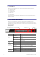
Parameter value/LAN 10Base 100Base 1000Base Max. collision domain DTE to DTE 100 meters 100 meters for UTP 412 meters for fiber 100 meters for UTP 316 meters for fiber Max. collision domain with repeater 2500 meters 205 meters 200 meters Slot time 512 bit times 512 bit times 512 bit times Interframe Gap 9.6us 0.96us 0.
A-3 Flow Control Flow control is a mechanism to tell the source device stopping sending frame for a specified period of time designated by target device until the PAUSE time expires. This is accomplished by sending a PAUSE frame from target device to source device. When the target is not busy and the PAUSE time is expired, it will send another PAUSE frame with zero time-to-wait to source device. After the source device receives the PAUSE frame, it will again transmit frames immediately.
the receiver of the target device begins receiving the bit stream, and looks for the PRE (Preamble) pattern and Start-of-Frame Delimiter (SFD) that indicates the next bit is the starting point of the MAC frame until all bit of the frame is received. For a received frame, the MAC will check: 1. If it is less than one slotTime in length, i.e. short packet, and if yes, it will be discarded by MAC because, by definition, the valid frame must be longer than the slotTime.
as a tagged VLAN frame. If this happens in a switch, the MAC will forward it, according to its priority and egress rule, to all the ports that is associated with that VID. If it happens in a network interface card, MAC will deprive of the tag header and process it in the same way as a basic normal frame. For a VLAN-enabled LAN, all involved devices must be equipped with VLAN optional function.
Index A Installation for VigorAPM, 6 L Account Manager, 88 B License Agreement, 23 License Information, 25, 26, 31, 37, 38, 45, 46, 51 Backup Manager, 86 Limiting Rate, 57 Bandwidth, 70 P C Preamble, 56 CoS Mapping, 67 D Properties, 58 Q Dashboard, 15, 16 QoS Configuration, 61 Diagnostics, 91 S DoS, 58 DoS Port Setting, 60 Security, 55 DoS Protection, 60 SNMP, 79 E SNMP Community, 81 Storm Control, 57 Egress Shaping Per Queue, 72 Storm Control, 56 Egress Shaping Rate, 71 F Factory