VigorSwitch G2240 User’s Guide Version: 1.0 Date: 2011/11/04 Copyright 2011 All rights reserved.
Copyright Information Copyright Declarations Copyright 2011 All rights reserved. This publication contains information that is protected by copyright. No part may be reproduced, transmitted, transcribed, stored in a retrieval system, or translated into any language without written permission from the copyright holders. Trademarks The following trademarks are used in this document: z Microsoft is a registered trademark of Microsoft Corp.
European Community Declarations Manufacturer: Address: Product: DrayTek Corp. No. 26, Fu Shing Road, HuKou Township, HsinChu Industrial Park, Hsin-Chu County, Taiwan 303 VigorSwitch Series Device The product conforms to the requirements of Electro-Magnetic Compatibility (EMC) Directive 2004/108/EC by complying with the requirements set forth in EN55022/Class A and EN55024/Class A.
Table of Contents 1 Preface ...............................................................................................................1 1.1 Overview ................................................................................................................................. 1 1.2 Features .................................................................................................................................. 3 1.3 Packing List..............................................................
2.5 GVRP Configuration.............................................................................................................. 56 2.5.1 GVRP Config .................................................................................................................. 57 2.5.2 Counter ........................................................................................................................... 59 2.5.3 Group .......................................................................................
2.16.2 Email ........................................................................................................................... 135 2.17 DHCP Snooping................................................................................................................ 136 2.17.1 DHCP Snooping State ................................................................................................ 136 2.17.2 DHCP Snooping Entry .................................................................................
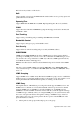
1 Preface In this user’s manual, it will not only tell you how to install and connect your network system but configure and monitor the 24 Gigabit L2 plus Switch through the built-in CLI and web by RS-232 serial interface and Ethernet ports step-by-step. Many explanations in detail of hardware and software functions are shown as well as the examples of the operation for web-based interface and command-line interface (CLI). 1.
Below shows key features of this device: QoS Support Quality of Service by the IEEE 802.1P standard. There are two priority queue and packet transmission schedule. Spanning Tree Support IEEE 802.1D, IEEE 802.1w (RSTP: Rapid Spanning Tree Protocol) standards. VLAN Support Port-based VLAN and IEEE802.1Q Tag VLAN. Support 256 active VLANs and VLAN ID 1~4094. Port Trunking Support static port trunking and port trunking with IEEE 802.3ad LACP.
¾ When one of its hosts joins a multicast address group to which none of its other hosts belong, sends unsolicited group membership reports to that group. ¾ When the last of its hosts in a particular multicast group leaves the group, sends an unsolicited leave group membership report to the all-routers group (244.0.0.2). 1.
z Supports port mirror function with ingress/egress traffic z Supports rapid spanning tree (802.1w RSTP) z Supports multiple spanning tree (802.1s MSTP) z Supports 802.1X port security on a VLAN z Supports IP-MAC-Port Binding for LAN security z Supports user management and only first login administrator can configure the device.
z 1000Mbps BiDi LC, type 2, SM 20km, SFP Fiber WDM transceiver z 1000Mbps LC, SM 10km, SFP Fiber transceiver with DDM Front View of 1000Base-SX/LX LC, SFP Fiber Transceiver Front View of 1000Base-LX BiDi LC, SFP Fiber Transceiver 1.4 LED Indicators and Connectors Before you use the Vigor device, please get acquainted with the LED indicators and connectors first. There are 24 TP Fast Ethernet ports and 2 slots for optional removable modules on the front panel of the switch.
User Interfaces on the Rear Panel One socket on the rear panel is for AC power input. 1.5 Hardware Installation At the beginning, please do first: ¾ Wear a grounding device to avoid the damage from electrostatic discharge ¾ Be sure you have inserted the power cord to power source 1.5.1 Connecting the SFP Fiber Transceiver to the Chassis The optional SFP modules are hot swappable, so you can plug or unplug it before or after powering on. 1.
After resetting, the bootloader will load the firmware into the memory. It will take about 30 seconds, after that, the switch will flash all the LED once and automatically performs self-test and is in ready state. 1.5.2 Installing Optional SFP Fiber Transceivers to the switch If you have no modules, please skip this section. 1.5.3 Installing Chassis to a 19-Inch Wiring Closet Rail Caution: Allow a proper spacing and proper air ventilation for the cooling fan at both sides of the chassis. 1.
Gigabit Ethernet TP network connection ¾ The grade of the cable must be Cat. 5 or Cat. 5e with a maximum length of 100 meters. Cat. 5e is recommended. Cabling Requirements for 1000SX/LX SFP Module It is more complex and comprehensive contrast to TP cabling in the fiber media. Basically, there are two categories of fiber, multi mode (MM) and single mode (SM). The later is categorized into several classes by the distance it supports. They are SX, LX, LHX, XD, and ZX.
Fiber Cable: 10.10/m Bit Time unit: 1ns (1sec./1000 Mega bit) TP to fiber Converter: 56 Bit Time unit: 0.01μs (1sec./100 Mega bit) Sum up all elements’ bit-time delay and the overall bit-time delay of wires/devices must be within Round Trip Delay (bit times) in a half-duplex network segment (collision domain). For full-duplex operation, this will not be applied. You may use the TP-Fiber module to extend the TP node distance over fiber optic and provide the long haul connection.
Case 2: Port-based VLAN -1 The same VLAN members could not be in different switches. Every VLAN members could not access VLAN members each other. The switch manager has to assign different names for each VLAN groups at one switch. Case 3: Port-based VLAN - 2 VLAN1 members could not access VLAN2, VLAN3 and VLAN4 members. VLAN2 members could not access VLAN1 and VLAN3 members, but they could access VLAN4 members. VLAN3 members could not access VLAN1, VLAN2 and VLAN4.
Case 4: The same VLAN members can be at different switches with the same VID VigorSwitch G2240 User’s Guide 11
1.5.5 Configuring the Management Agent of Switch We offer you three ways to startup the switch management function. They are RS-232 console, CLI, and Web. Users can use any one of them to monitor and configure the switch. You can touch them through the following procedures.
4. Data bits 8 Parity N Flow control none When you complete the connection, then press key. The login prompt will be shown on the screen. The default username and password are shown as below: Username = admin Password = admin Additionally, if a user connects VigorSwitch to VigorPro router, he also can access into VigorPro web configuration page to find out External Devices menu item. Then click the new added switch icon to open the web configuration of VigorSwitch.
Configuring the Management Agent of VigorSwitch G2240 through the Ethernet Port There are three ways to configure and monitor the switch through the switch’s Ethernet port. They are CLI, Web browser and SNMP manager. The user interface for the last one is NMS dependent and does not cover here. We just introduce the first two types of management interface.
1. Set up a physical path between the configured the switch and a PC by a qualified UTP Cat. 5 cable with RJ-45 connector. Note: If PC directly connects to the switch, you have to setup the same subnet mask between them. But, subnet mask may be different for the PC in the remote site. 2. Run CLI or web browser and follow the menu. Please refer to Chapter 2.
1.5.6 IP Address Assignment For IP address configuration, there are three parameters needed to be filled in. They are IP address, Subnet Mask, Default Gateway and DNS. IP address: The address of the network device in the network is used for internetworking communication. Its address structure looks is shown below. It is “classful” because it is split into predefined address classes or categories. Each class has its own network range between the network identifier and host identifier in the 32 bits address.
Class D and E: Class D is a class with first 4 MSB (Most significance bit) set to 1-1-1-0 and is used for IP Multicast. See also RFC 1112. Class E is a class with first 4 MSB set to 1-1-1-1 and is used for IP broadcast. According to IANA (Internet Assigned Numbers Authority), there are three specific IP address blocks reserved and able to be used for extending internal network. We call it Private IP address and list below: Class A 10.0.0.0 --- 10.255.255.255 Class B 172.16.0.0 --- 172.31.255.
In this diagram, you can see the subnet mask with 25-bit long, 255.255.255.128, contains 126 members in the sub-netted network. Another is that the length of network prefix equals the number of the bit with 1s in that subnet mask. With this, you can easily count the number of IP addresses matched. The following table shows the result. Prefix Length No. of IP matched No.
First, IP Address: as shown above, enter “192.168.1.1”, for instance. For sure, an IP address such as 192.168.1.x must be set on your PC. Second, Subnet Mask: as shown above, enter “255.255.255.0”. Any subnet mask such as 255.255.255.x is allowable in this case. DNS: The Domain Name Server translates human readable machine name to IP address. Every machine on the Internet has a unique IP address. A server generally has a static IP address.
1.6 Typical Applications The 24-Port PoE L2 Managed Fast Ethernet Switch with 2 SFP Dual Media implements 24 Fast Ethernet TP ports with auto MDIX and 2 Gigabit dual media ports with SFP for removable module supported comprehensive fiber types of connection, including LC, BiDi LC for SFP. For more details on the specification of the switch, please refer to Appendix A. The switch is suitable for the following applications.
¾ Peer-to-peer application is used in two remote offices ¾ Office Network Connection VigorSwitch G2240 User’s Guide 21
22 VigorSwitch G2240 User’s Guide
2 Operation of Web-based Management This chapter instructs you how to configure and manage the switch through the web user interface it supports, to access and manage the 22-Port 10/100Mbps TP and 2-Port Gigabit TP/SFP Fiber management Ethernet switch.
2.1 Web Management Home Overview After you login, the switch shows you the system information as below. This page is default and tells you the basic information of the system, including “Model Name”, “System Description”, “Location”, “Contact”, “Device Name”, “System Up Time”, “Current Time”, “BIOS Version”, “Firmware Version”, “Hardware-Mechanical Version”, “Serial Number”, “Host IP Address”, “Host MAC Address”, “Device Port”, “RAM Size”, “Flash Size” and “CPU Load”.
2.1.1 The Information of Page Layout On the top side, it shows the front panel of the switch. In the front panel, the linked ports will display green; as to the ports, which are link off, they will be dark. For the optional modules, the slot will show only a cover plate if no module exists and will show a module if a module is present. The image of module depends on the one you inserted. The same, if disconnected, the port will show just dark, if linked, green.
2.1.2 System Information Function name: System Information Function description: Show the basic system information.
Parameter description: Model name: The model name of this device. System description: Display what the device’s description. Location: Set the location of the switch where it was located. Contact: For easily managing and maintaining device, you may write down the contact person and phone here for getting help soon. You can configure this parameter through the device’s user interface or SNMP. Device name: The name of the switch, User-defined. Default is VigorSwitch G2240.
CPU Load: The loading of the CPU on this switch. 2.1.3 Account Configuration In this function, only administrator can create, modify or delete the username and password. Administrator can modify other guest identities’ password without confirming the password but it is necessary to modify the administrator-equivalent identity. Guest-equivalent identity can modify his password only.
Set the system time by manual input or set it by syncing from Time servers. The function also supports daylight saving for different area’s time adjustment. Parameter description: Current Time: Show the current time of the system. Manual: This is the function to adjust the time manually. Filling the valid figures in the fields of Year, Month, Day, Hour, Minute and Second respectively and press button, time is adjusted.
to the starting date and the ending date. For example, if you set the day light saving to be 1 hour. When the time passes over the starting time, the system time will be increased one hour after one minute at the time since it passed over. And when the time passes over the ending time, the system time will be decreased one hour after one minute at the time since it passed over. The switch supports valid configurable day light saving time is –5 ~ +5 step one hour.
Parameter description: DHCP Setting: DHCP is the abbreviation of Dynamic Host Configuration Protocol. Here DHCP means a switch to turn ON or OFF the function. The switch supports DHCP client used to get an IP address automatically if you set this function “Enable”. When enabled, the switch will issue the request to the DHCP server resided in the network to get an IP address.
is shown in the following figure. This reduces the total IP number of a network able to support, by the amount of 2 power of the bit number of subnet number (2^(bit number of subnet number)). Subnet mask is used to set the subnet mask value, which should be the same value as that of the other devices resided in the same network it attaches. For more information, please also see the Section 2-1-5 “IP Address Assignment” in this manual. Default: 255.255.255.
Parameter description: Port No: Display the port number. The number is 1 – 24. Detection Port - Enable: When Port No is chosen, and enable port's Loop detection, the port can detect loop happens. When Port-No is chosen, enable port's Loop detection, and the port detects loop happen, port will be locked. If Loop did not happen, port maintains Unlocked. Locked Port - Resume: When Port No is chosen, enable port's Loop detection, and the port detects loop happen, the port will be locked.
Rule 4): When both “accept and deny” lists exist, then it will deny all connections, excluding the connection inside of the accepting range. Rule 5): When both “accept and deny” lists exist, then it will deny all connections, excluding the connection inside of the accepting range and NOT inside of the denying range at the same time. Function name: Management Policy List Function description: The switch offers Management Policy List function.
Name: A name is composed of any letter (A-Z, a-z) and digit (0-9) with maximal 8 characters. IP Range: The switch supports two kinds of options for managed valid IP Range, including “Any” and “Custom”. Default is “Any”. In case that “Custom” had been chosen, you can assign effective IP range. The valid range is 0.0.0.0~255.255.255.255. Access Type: The switch supports two kinds of options for managed valid Access Type, including “Any” and “Custom”. Default is “Any”.
2.1.8 System Log The System Log provides information about system logs, including information when the device was booted, how the ports are operating, when users logged in, when sessions timed out, as well as other system information. Function name: System Log Function description: The Trap Log Data is displaying the log items including all SNMP Private Trap events, SNMP Public traps and user logs occurred in the system. In the report table, No.
appear on the top of its Web UI. By pressing these buttons, user will be allowed to connect the Web UI of the devices of the group in the same window without the login of these devices. The most top-left button is only for Master device. The background color of the button you press will be changed to represent that the device is under your management. Note: It will remove the grouping temporarily in case that you login the switch via the console.
2.2 Port Configuration Four functions, including Port Status, Port Configuration, Simple Counter and Detail Counter are contained in this function folder for port monitor and management. Each of them will be described in detail orderly in the following sections. 2.2.1 Port Configuration Port Configuration is applied to change the setting of each port. In this configuration function, you can set/reset the following functions. All of them are described in detail below.
Media type NWay 1000M TP ON/OFF 1000M Fiber ON/OFF Speed Duplex 10/100/1000M Full for all, Half for 10/100 1000M Full In Auto-negotiation mode, no default value. In Forced mode, default value depends on your setting. Flow Control: There are two modes to choose in flow control, including Enable and Disable. If flow control is set Enable, both parties can send PAUSE frame to the transmitting device(s) if the receiving port is too busy to handle.
Function Description: Report the latest updated status of all ports in this switch. When any one of the ports in the switch changes its parameter displayed in the page, it will be automatically refreshed the port current status about every 5 seconds. Parameter Description: Port: Display the port number. The number is 1 – 24. Both port 21 ~ 24 are optional modules. Link: Show that if the link on the port is active or not.
Note: If you want to get the below detail information then you need to click right button of mouse on SFP icon. Connector Type: Display the connector type, for instance, UTP, SC, ST, LC and so on. Fiber Type: Display the fiber mode, for instance, Multi-Mode, Single-Mode. Tx Central Wavelength: Display the fiber optical transmitting central wavelength, for instance, 850nm, 1310nm, 1550nm and so on.
Mon3(RX PWR): Show the receiver power of SFP module. 2.2.3 Simple Counter The function of Simple Counter collects any information and provides the counting about the traffic of the port, no matter the packet is good or bad. In the following figure, the window can show all ports’ counter information at the same time. Each data field has 20-digit long. If the counting is overflow, the counter will be reset and restart counting. The data is updated every time interval defined by the user.
2.2.4 Detail Counter The function of Detail Counter collects any information and provides the counting about the traffic of the port, no matter the packet is good or bad. In the following figure, the window can show only one port counter information at the same time. To see another port’s counter, you have to pull down the list of Select, then you will see the figures displayed about the port you had chosen. Each data field has 20-digit long.
44 RX 512-1023 Bytes: Number of 512 ~ 1023-byte frames in good and bad packets received. RX 1024- 1522 Bytes: Number of 1024-1522-byte frames in good and bad packets received. RX 1527 Bytes: Number of 1527-byte frames in good and bad packets received. Rx Drops: Number of frames dropped due to the lack of receiving buffer. Rx CRC/Alignment: Number of Alignment errors packets received. Rx Undersize: Number of short frames (<64 Bytes) with valid CRC.
2.3 VLAN The switch supports Tag-based VLAN (802.1q) and Port-based VLAN. Support 256 active VLANs and VLAN ID 1~4094. VLAN configuration is used to partition your LAN into small ones as your demand. Properly configuring it, you can gain not only improving security and increasing performance but greatly reducing VLAN management. 2.3.
Each tag-based VLAN you built up must be assigned VLAN name and VLAN ID. Valid VLAN ID is 1-4094. User can create total up to 64 Tag VLAN groups. 2.3.2 Tag-based Group Function name: Tag-based Group Function description: It shows the information of existed Tag-based VLAN Groups, You can also easily create, edit and delete a Tag-based VLAN group by pressing , and function buttons. User can add a new VLAN group by inputting a new VLAN name and VLAN ID.
You enable IGMP on the interfaces that connect the system to its hosts that are farther away from the root of the tree. These interfaces are known as downstream interfaces. PVLAN: Private VLAN ID identifier. Each Private VLAN group has a unique VID. Private VLAN contains switch ports that cannot communicate with each other but can access another network. It appears only in tag-based and Double-tag mode. GVRP-P: GVRP Propagation identifier.
2.3.3 Port-based Group Function name: Port-based Group Function description: It shows the information of the existed Port-based VLAN Groups. You can easily create, edit and delete a Port-based VLAN group by pressing , and function buttons. User can add a new VLAN group by inputting a new VLAN name. Parameter description: 48 VLAN Name: The name defined by administrator is associated with a VLAN group. Valid letters are A-Z, a-z, 0-9, “ - “ and “_” characters.
Delete Just press the button to remove the selected group entry from the Port-based group table. 2.3.4 Ports Function name: VLAN Port Configuration Function description: In VLAN Tag Rule Setting, user can input VID number to each port. The range of VID number is from 1 to 4094. User also can choose ingress filtering rules to each port. There are two ingress filtering rules which can be applied to the switch.
packets carry no VLAN tag header. If packets have double VLAN tags, one will be dropped and the other will still be left. As to Hybrid, it is similar to Trunk, and both of them will tag-out. When the port is set to Hybrid, its packets will be untagged out if the VID of the outgoing packets with tag is the same as the one in the field of Untag VID of this port. Untag VID: Valid range is 1~4094. It works only when Role is set to Hybrid.
2.3.6 Management VLAN Function name: Management VLAN Function description: To create a secure VLAN for the switch management interface, all of the management traffic will be sent via an isolated VLAN. This is a security function. It can protect switch management interface, it also can avoid the switch CPU DoS by network attacking. Parameter description: VID: Valid range 1~4094. 2.
Parameter description: 52 Aging Time: Delete a MAC address idling for a period of time from the MAC Table, which will not affect static MAC address. Range of MAC Address Aging Time is 10-1000000 seconds. The default Aging Time is 300 seconds. Disable automatic aging: Stop the MAC table aging timer, the learned MAC address will not age out automatically Auto: Enable this port MAC address dynamic learning mechanism.
2.4.2 Static Filter Function Name: Static Filter Function Description: Static Filter is a function that denies the packet forwarding if the packet’s MAC Address is listed in the filtering Static Filter table. User can very easily maintain the table by filling in MAC Address, VID (VLAN ID) and Alias fields individually. User also can delete the existed entry by clicking button.
2.4.3 Static Forward Function Name: Static Forward Function Description: Static Forward is a function that allows the user in the static forward table to access a specified port of the switch. Static Forward table associated with a specified port of a switch is set up by manually inputting MAC address and its alias name. When a MAC address is assigned to a specific port, all of the switch’s traffics MAC address will be forwarded to this port.
2.4.4 MAC Alias Function name: MAC Alias Function description: MAC Alias function is used to let you assign MAC address a plain English name. This will help you tell which MAC address belongs to which user in the illegal access report. At the initial time, it shows all pairs of the existed alias name and MAC address. There are three MAC alias functions in this function folder, including MAC Alias Add, MAC Alias Edit and MAC Alias Delete.
2.4.5 MAC Table Function name: MAC Table Function description: Display the static or dynamic learning MAC entry and the state for the selected port. Parameters description: Port: The port that exists in the searched MAC Entry. Search: Find the specific MAC address what you input for search. Previous Page: Move to the previous page. Next Page: Move to the next page. 2.5 2.
2.5.1 GVRP Config Function name: GVRP Config Function description: In the function of GVRP Config, it is used to configure each port’s GVRP operation mode, in which there are seven parameters needed to be configured described below. Parameter description: GVRP State Setting: This function is simply to let you enable or disable GVRP function. You can pull down the list and click the arrow key to choose “Enable” or “Disable”.
switch does not send or reply any GARP messages. It just listens messages and reacts for the received GVRP BPDU. Default Registrar Mode: The mode here means the type of Registrar. There are three types of parameters for registrar administrative control value, normal registrar, fixed registrar and forbidden registrar, provided for the user’s choice. Normal - It is Normal Registration. The Registrar responds normally to incoming GARP messages. The default setting is Normal. Fixed - It is Registration Fixed.
2.5.2 Counter Function name: GVRP Counter Function description: All GVRP counters are mainly divided into Received and Transmitted two categories to let you monitor the GVRP actions. Actually, they are GARP packets. Parameter description: Received: Total GVRP Packets: Total GVRP BPDU is received by the GVRP application. Invalid GVRP Packets: Number of invalid GARP BPDU is received by the GARP application.
Invalid GVRP Packets: Number of invalid GARP BPDU is transmitted by the GVRP application. LeaveAll Message Packets:Number of GARP BPDU with Leave All message is transmitted by the GARP application. JoinEmpty Message Packets:Number of GARP BPDU with Join Empty message is transmitted by the GARP application. JoinIn Message Packets:Number of GARP BPDU with Join In message is transmitted by the GARP application.
2.6 QoS (Quality of Service) Configuration The switch support four QoS queues per port with strict or weighted fair queuing scheduling. There are 24 QoS Control Lists (QCL) for advance programmable QoS classification, based on IEEE 802.1p, Ethertype, VID, IPv4/IPv6 DSCP and UDP/TCP ports and ranges. High flexibility in the classification of incoming frames to a QoS class.
Default Class: User can set up High Priority or Low Priority for each port respectively. Low / Normal / Medium / High QCL: The number of QCL rule 1~24, each port have to apply one of the QCL rule for QoS behavior User Priority: The user priority value 0~7 (3 bits) is used as an index to the eight QoS class values for VLAN tagged or priority tagged frames. Queuing Mode: There are two Scheduling Method, Strict Priority and Weighted Fair. Default is Strict Priority.
Parameter description: QCL#: QCL number : 1~24 QCE Type: Ethernet Type / VLAN ID / UDP/TCP Port / DSCP / ToS / Tag Priority Ethernet Type Value: The configurable range is 0x600~0xFFFF. Well known protocols already assigned EtherType values. The commonly used values in the EtherType field and corresponding protocols are listed below: Ethertype (Hexadecimal) VigorSwitch G2240 User’s Guide Protocol 0x0800 IP, Internet Protocol 0x0801 X.
0x880B PPP, Point-to-Point Protocol. 0x 880C GSMP, General Switch Management Protocol. 0x8847 MPLS, Multi-Protocol Label Switching (unicast). 0x8848 MPLS, Multi-Protocol Label Switching (multicast). 0x8863 PPPoE, PPP Over Ethernet (Discovery Stage). 0x8864 PPPoE, PPP Over Ethernet (PPP Session Stage). 0x88BB LWAPP, Light Weight Access Point Protocol. 0x88CC LLDP, Link Layer Discovery Protocol. 0x8E88 EAPOL, EAP over LAN. 0x9000 Loopback (Configuration Test Protocol) 0xFFFF reserved.
VigorSwitch G2240 User’s Guide 65
Parameter description: VLAN ID: The configurable VID range:1~4094 UDP/TCP Port: To select the UDP/TCP port classification method by Range or Specific. UDP/TCP Port Range: The configurable ports range: 0~65535 You can refer to following UDP/TCP port-numbers information. http://www.iana.org/assignments/port-numbers UDP/TCP Port No.: The configurable specific port value: 0~65535 DSCP Value: The configurable DSCP value: 0~63 Traffic Class: Low / Normal / Medium / High 2.6.
Ingress Unit: There are two units for ingress rate limit: kbps / Mbps Egress Enabled: Shaper enabled to limit egress bandwidth by egress rate. Egress Rate: The configurable shaper rate range: 500 Kbps ~ 1000000 Kbps 1 Mbps ~ 1000 Mbps Egress Unit: There are two units for egress shaper rate limit: kbps / Mbps 2.6.
2.6.5 Wizard Function name: Wizard Function description: The QCL configuration Wizard is targeted on user can easy to configure the QCL rules for QoS configuration. The wizard provide the typical network application rules, user can apply these application easily.
z Set up Port Policies Parameter description: QCL ID: QoS Control List (QCL): 1~24 Port Member: Port Member: 1~24 Next: Go to next step. Cancel: Abort current configuration back to previous step. Back: Back to previous screen. Wizard Again: Click on the , back to QCL Configuration Wizard.
screen, then ask you to click on for changed parameters confirmation.
z Set up Typical Network Application Rules Parameter description: Audio and Video: QuickTime 4 Server / MSN Messenger Phone / Yahoo Messenger Phone / Napster / Real Audio Games: Blizzard Battlenet (Diablo2 and StarCraft) / Fighter Ace II / Quake2 / Quake3 / MSN Game Zone User Definition: Ethernet Type / VLAN ID / UDP/TCP Port / DSCP Ethernet Type Value: Type Range: 0x600~0xFFFF VLAN ID: VLAN ID Range: 1~4094 UDP/TCP Port: Two Mode: Range / Specific UDP/TCP Port Range: Port Range: 0~65535 UDP/TCP Port
72 QCL ID: QCL ID Range: 1~24 Traffic Class: There are four classes: Low / Normal / Medium / High Next: Go to next step. Cancel: Abort current configuration back to previous step. Back: Back to previous screen. Wizard Again: Click on the , back to QCL Configuration Wizard. Finish: When you click on , the parameters will be set according to the wizard configuration and shown on the screen, then ask you to click on for changed parameters confirmation.
z Set up TOS Precedence Mapping Parameter description: QCL ID: QoS Control List (QCL): 1~24 TOS Precedence 0~7 Class: Low / Normal / Medium / High Next: Go to next step. Cancel: Abort current configuration back to previous step. Back: Back to previous screen.
74 Wizard Again: Click on the , back to QCL Configuration Wizard. Finish: When you click on , the parameters will be set according to the wizard configuration and shown on the screen, then ask you to click on for changed parameters confirmation.
z Set up VLAN Tag Priority Mapping Parameter description: QCL ID: QoS Control List (QCL): 1~24 Tag Priority 0~7 Class: Low / Normal / Medium / High Next: Go to next step. Cancel: Abort current configuration back to previous step. Back: Back to previous screen. Wizard Again: Click on the , back to QCL Configuration Wizard.
screen, then ask you to click on for changed parameters confirmation. 2.7 SNMP Configuration Any Network Management System (NMS) running the Simple Network Management Protocol (SNMP) can manage the Managed devices equipped with SNMP agent, provided that the Management Information Base (MIB) is installed correctly on the managed devices.
Parameters description: SNMP: The term SNMP here is used for the activation or de-activation of SNMP. Default is Enable. Get/Set/Trap Community: Community name is used as password for authenticating if the requesting network management unit belongs to the same community group. If they both don’t have the same community name, they don’t belong to the same group.
user-definable. To set up a trap host means to create a trap manager by assigning an IP address to host the trap message. In other words, the trap host is a network management unit with SNMP manager receiving the trap message from the managed switch with SNMP agent issuing the trap message. 6 trap hosts can prevent the important trap message from losing. For each public trap, the switch supports the trap event Cold Start, Warm Start, Link Down, Link Up and Authentication Failure Trap.
Parameters description: Port #: Port number: 1~24 Policy ID: Policy ID range: 1~8 Action: Permit or Deny forwarding the met ACL packets Rate Limiter ID: Disabled: Disable Rate Limitation Rate Limiter ID Range: 1~16. To select one of rate limiter ID for this port, it will limit met ACL packets by rate limiter ID configuration. Port Copy: Disabled: Disable to copy the met ACL packets to specific port Port number: 1~24.
2.8.2 Rate Limiters Function name: ACL Rate Limiter Configuration Function description: There are 16 rate limiter IDs. You can assign one of the limiter ID for each port. The rate limit configuration unit is Packet Per Second (pps).
2.8.3 Access Control List Function name: ACL Control List Configuration Function description: The switch ACL function support up to 128 Access Control Entries (ACEs), using the shared 128 ACEs for ingress classification. You can create an ACE and assign this ACE for each port with or assign this ACE for a policy or assign this ACE for a port.
ARP: It is including all ARP protocol frame type IPv4: It is including all IPv4 protocol frame type To insert an entry, click the icon of inserting an entry, the following page will be shown as below. The switch ACL function support up to 128 Access Control Entries (ACEs), using the shared 128 ACEs for ingress classification. You can create an ACE and assign this ACE for each port with or assign this ACE for a policy or assign this ACE for a port.
ARP: It is including all ARP protocol frame type. When you choose this one, the following selection will appear. IPv4: It is including all IPv4 protocol frame type. When you choose this one, the following selection will appear. MAC Parameters: This section will change slightly based on the frame type selected.
MC: It is including all Multicast MAC address BC: It is including all Broadcast MAC address UC: It is including all Unicast MAC address (When Frame Type = Ethernet Type) EtherType Filter: Range: Any / Specific Any: It is including all Ethernet frame type Specific: It is according to specific Ethernet Type Value. Ethernet Type Value: The Ethernet Type Range: 0x600-0xFFFF ARP Parameters: This selection appears when Frame Type = ARP.
0: The ingress ARP/PARP frames where the Hardware size is not equal "0x6" or the Protocol size is not equal "0x4" 1: The ingress ARP/PARP frames where the Hardware size is equal "0x6" and the Protocol size is "0x4" IP: Range: Any / 0 / 1 Any: Both 0 and 1 0: The ingress ARP/PARP frames where Protocol type is not equal "0x800" 1: The ingress ARP/PARP frames where Protocol type is equal "0x800" Ethernet: Range: Any / 0 / 1 Any: Both 0 and 1 0: The ingress ARP/PARP frames where Hardware type is not equal "0x10
DIP Filter: (DIP Destination IP Address) Range: Any / Host / Network Any: Including all destination IP address Host: Only one specific destination host IP address Network: A specific IP subnet segment under the destination IP mask DIP Address: Default: 192.168.1.254 DIP Mask: Default: 255.255.255.
for ingress classification Source Port No.: Range: 0-65535 Source Port Range.: Range: 0-65535 Dest. Port Filter: Range: Any / Specific / Range Any: Including all TCP destination ports Specific: According to following Dest. Port No. setting for ingress classification Range: According to following Dest. Port Range setting for ingress classification Dest. Port No.: Range: 0-65535 Dest. Port Range.
IP Protocol Value: Default: 255 IPTTL: (Time To Live) How many routers a datagram can pass through. Each router decrements this value by 1 until it reaches 0 when the datagram is discarded. This keeps misrouted datagrams from remaining on the Internet forever. Range: Any / Non-zero / Zero Any: Including all conditions for IPTTL Non-Zero: Including IPTTL is Non-Zero Zero: Including IPTTL is zero IP Fragment: (IP Fragmentation Flag) Controls datagram fragmentation together with the identification field.
Action: Range: Permit / Deny Permit: Permit the met ACL ingress classification rule packets forwarding to other ports on the switch Deny: Discard the met ACL ingress classification rule packets Rate Limiter: Range: Disabled / 1-16 Disable: Disable Rate Limiter function 1-16: Apply the Rate Limiter Number setting for met ACL ingress rule packets Port Copy: Range: Disabled / 1-24 Disable: Disable the Port Copy function 1-24: The packets will be copied to the selected port when they met ACL ingress rule. 2.8.
z 90 Set up Policy Rules Cancel: Cancel current setting back to top layer in the ACL wizard function. Back: Click on to back to previous step. Next: Click on to go to the next step. Wizard Again: Click on the UI will back to top layer in the wizard function. Finish: Click in to finish the ACL Wizard setting, it will according the selection items to change the related parameters, then you have to click on to confirm the all changed parameters setting.
z Set up Port Policies Cancel: Cancel current setting back to top layer in the ACL wizard function. Back: Click on to back to previous step. Next: Click on to go to the next step.
92 Wizard Again: Click on the UI will back to top layer in the wizard function. Finish: Click in to finish the ACL Wizard setting, it will according the selection items to change the related parameters, then you have to click on to confirm the all changed parameters setting.
z Set up Typical Network Application Rules Common Server: DHCP / DNS / FTP / HTTP / IMAP / NFS / POP3 / SAMBA / SMTP / TELNET / TFTP Instant Messaging: Google Talk / MSN Messenger / Yahoo Messenger User Definition: Ethernet Type / UDP Port / TCP Port Others: TCP Port / ICMP / Multicast IP Stream / NetBIOS / Ping Request / Ping Reply / SNMP / SNMP Traps Cancel: Cancel current setting back to top layer in the ACL wizard function. Back: Click on to back to previous step.
94 Ingress Port: Any / Policy1-8 / Port1-24 Action: Permit / Deny Rate Limiter ID: Disabled / 1-16 Cancel: Cancel current setting back to top layer in the ACL wizard function. Back: Click on to back to previous step. Next: Click on to go to the next step. Wizard Again: Click on the UI will back to top layer in the wizard function.
then you have to click on to confirm the changed parameters setting.
2.9 IP MAC Binding 2.9.1 IP MAC Binding Configuration The IP network layer uses a four-byte address. The Ethernet link layer uses a six-byte MAC address. Binding these two address types together allows the transmission of data between the layers. The primary purpose of IP-MAC binding is to restrict the access to a switch to a number of authorized users. Only the authorized client can access the Switch’s port by checking the pair of IP-MAC Addresses and port number with the pre-configured database.
Add: Input MAC, IP, Port and VID, then click on to create a new entry into the IP MAC Binding table Delete: Select one of entry from the table, then click on to delete this entry. 2.9.2 IP MAC Binding Dynamic Entry The function must combine with IP-MAC Binding and DHCP Snooping Enable. No: The IP-MAC Binding entry Index MAC: Six-byte MAC Address: xx-xx-xx-xx-xx-xx For example: 00-40-c7-00-00-01 IP: Four-byte IP Address: xxx.xxx.xxx.xxx For example: 192.168.1.100 Port No: Port no.
2.10 802.1X Configuration 802.1X port-based network access control provides a method to restrict users to access network resources via authenticating user’s information. This restricts users from gaining access to the network resources through a 802.1X-enabled port without authentication. If a user wishes to touch the network through a port under 802.
The overview of operation flow for the Fig. 3-52 is quite simple. When Supplicant PAE issues a request to Authenticator PAE, Authenticator and Supplicant exchanges authentication message. Then, Authenticator passes the request to RADIUS server to verify. Finally, RADIUS server replies if the request is granted or denied.
The figure below shows the procedure of 802.1X authentication. There are steps for the login based on 802.1X port access control management. The protocol used in the right side is EAPOL and the left side is EAP. 1. At the initial stage, the supplicant A is unauthenticated and a port on switch acting as an authenticator is in unauthorized state. So the access is blocked in this stage. 2. Initiating a session. Either authenticator or supplicant can initiate the message exchange.
connected to the supplicant and under 802.1X control is in the authorized state. The supplicant and other devices connected to this port can access the network. If the authenticator receives a Radius-Access-Reject, it will send an EAP-Failure to the supplicant. This means the supplicant is failed to authenticate. The port it connected is in the unauthorized state, the supplicant and the devices connected to this port won’t be allowed to access the network. 10.
2.10.1 Server Function name: 802.1X Server Configuration Function description: This function is used to configure the global parameters for RADIUS authentication in 802.1X port security application. Authentication Server Server IP Server - Server IP address for authentication. Default: 192.168.1.1 UDP Port -Default port number is 1812. Secret Key - The secret key should be between authentication server and authenticator. It is a string with the length 1 – 31 characters.
This function is used to configure the parameters for each port in 802.1X port security application. Refer to the following parameters description for details. Parameter description: Port: It is the port number to be selected for configuring its associated 802.1X parameters which are Port control, reAuthMax, txPeriod, Quiet Period, reAuthEnabled, reAuthPeriod, max. Request, suppTimeout, serverTimeout and Controlled direction.
reAuthMax(1-10): The number of authentication attempt that is permitted before the port becomes unauthorized. Default: 2 txPeriod(1-65535 s): A time period to transmitted EAPOL PDU between the authenticator and the supplicant. Default: 30 Quiet Period (0-65535 s): A period of time during which we will not attempt to access the supplicant. Deafult: 60 seconds reAuthEnabled: Choose whether regular authentication will take place in this port.
Parameter description: Port: Port number: 1-24 Mode: Show this port IEEE 802.1X operating mode: There are four modes Disable, Normal, Advance and Clientless. Status: Show this port IEEE 802.1X security current status: Authorized or Unauthorized. 2.10.4 Statistics Function name: 802.1X Port Statistics Port 1 Function description: Show the IEEE 802.1X authentication related counters for manager monitoring authenticator status.
2.11 Trunking Configuration The Port Trunking Configuration is used to configure the settings of Link Aggregation. You can bundle more than one port with the same speed, full duplex and the same MAC to be a single logical port, thus the logical port aggregates the bandwidth of these ports. This means you can apply your current Ethernet equipments to build the bandwidth aggregation.
z A port using the “None“ trunking method or Group ID 0 will be automatically set to use the “None” trunking method with Group ID 0. 2.11.1 Port Function name: Trunk Port Setting/Status Function description: Port setting/status is used to configure the trunk property of each and every port in the switch system. Parameter description: Port : Port Number: 1-24 Method: This determines the method a port uses to aggregate with other ports.
Passive - A Passive LACP port will not actively send LACPDU out before it receives an LACPDU from its link partner. Aggtr: Aggtr is an abbreviation of “aggregator”. Every port is also an aggregator, and its own aggregator ID is the same as its own Port No. We can regard an aggregator as a representative of a trunking group. Ports with same Group ID and using same trunking method will have the opportunity to aggregate to a particular aggregator port.
LACP Detail Function name: LACP Detail (LACP Aggregator Detailed Information) Function description: Show the detailed information of the LACP trunking group. Parameter description: Actor: The switch you are watching on. Partner: The peer system from this aggregator’s view. System Priority: Show the System Priority part of a system ID. MAC Address: Show the MAC Address part of a system ID. Port: Show the port number part of an LACP port ID. Key: Show the key value of the aggregator.
2.11.3 Aggregation Hash Mode Function name: Aggregation Hash Mode Function description: Configure the current port aggregate mode with 4 types. Parameter description: 110 Source MAC Address: Check this box to evoke to enable source MAC address for Aggregate Mode. Destination MAC Address: Check this box to evoke to enable destination MAC address for Aggregate Mode. IP Address: Check this box to evoke to enable IP address for Aggregate Mode.
2.11.4 LACP System Priority Function name: LACP System Priority Function description: It is used to set the priority part of the LACP system ID. LACP will only aggregate together the ports whose peer link partners are all on a single system. Each system supports LACP will be assigned a globally unique System Identifier for this purpose. A system ID is a 64-bit field comprising a 48-bit MAC Address and 16-bit priority value. The System Priority can be set by the user. Its range is from 1 to 65535.
Parameter description: STP State: Show the current STP Enabled / Disabled status. Default is “Disabled”. Bridge ID: Show switch’s bridge ID which stands for the MAC address of this switch. Bridge Priority: Show this switch’s current bridge priority setting. Default is 32768. Designated Root: Show root bridge ID of this network segment. If this switch is a root bridge, the “Designated Root” will show this switch’s bridge ID. Designated Priority: Show the current root bridge priority.
Hello Time: Show the current hello time of the root bridge. Hello time is a time interval specified by root bridge, used to request all other bridges periodically sending hello message every “hello time” seconds to the bridge attached to its designated port. STP Topology Change Count: STP Topology Change Count expresses the time spent in unit of seconds since the beginning of the Spanning Tree Topology Change to the end of the STP convergence.
Parameter description: Spanning Tree Protocol: Set 802.1W Rapid STP function Enable / Disable. Default is “Disable” Bridge Priority: The lower the bridge priority is, the higher priority it has. Usually, the bridge with the highest bridge priority is the root. If you want to have the switch as root bridge, you can set this value lower than that of bridge in the LAN. The valid value is 0 ~ 61440. The default is 32768.
2.12.3 Port Function name: STP Port Configuration Function description: In the STP Port Setting, one item selection and five parameters settings are offered for user’s setup. User can disable and enable each port by selecting each Port Status item. User also can set “Path Cost” and “Priority” of each port by filling in the desired value and set “Admin Edge Port” and “Admin Point To Point” by selecting the desired item. Parameter description: Port Status: It displays the current state of a port.
Configured Path Cost: The range is 0 – 200,000,000. In the switch, if path cost is set to be zero, the STP will get the recommended value resulted from auto-negotiation of the link accordingly and display this value in the field of Path Cost Status. Otherwise, it may show the value that the administrator set up in Configured Path Cost and Path Cost Status. 802.
2.13 MSTP The implementation of MSTP is according to IEEE 802.1Q 2005 Clause 13 – Multiple Spanning Tree Protocol. MSTP allows frames assigned to different VLANs to follow separate paths, each based on an independent Multiple Spanning Tree Instance (MSTI), within Multiple Spanning Tree (MST) Regions composed of LANs and or MST Bridges. Proper configuration of MSTP in an 802.1Q VLAN environment can ensure a loop-free data path for a group of vlans within an MSTI.
2.13.2 Region Config Function name: MSTP Region Config Function description: Configure the basic identification of a MSTP bridge. Bridges participating in a common MST region must have the same Region Name and Revision Level. Parameter description: 118 Region Name: 0-32 characters (A variable length text string encoded within a fixed field of 32 octets, conforming to RFC 2271’s definition of SnmpAdminString.
2.13.3 Instance View Function name: MSTP Instance View Function description: Provide an MST instance table which includes information (vlan membership of a MSTI) of all spanning instances provisioned in the particular MST region which the bridge belongs to. Through this table, additional MSTP configuration data can be applied and MSTP status can be retrieved. Parameter description: Instance ID: Every spanning tree instance need to have a unique instance ID within 0~4095.
z Edit MSTI / Vlan Instance ID: Every spanning tree instance need to have a unique instance ID within 0~4095. Instance 0 (CIST) always exists and can not be deleted. Additional spanning instances (MSTIs) can be added or deleted. At least one vlan must be provisioned for an MSTI to declare the need for the MSTI to be existent. Vlan Mapping: VID STRING VID STRING Example: 2.5-7.100-200.301.303.
32768 / 36864 / 40960 / 45056 / 49152 / 53248 / 57344 / 61440 MAX. Age: 6-40sec, same definition as in the RSTP protocol. Forward Delay: 4-30sec, same definition as in the RSTP protocol. MAX. Hops: 6-40sec. It’s a new parameter for the multiple spanning tree protocol. It is used in the internal spanning tree instances. “CIST Remaining Hops” or “MSTI Remaining Hops” in the Spanning tree protocol message would decreased by one when the message is propagated to the neighboring bridge.
Admin P2P: Auto / True / False The same definition as in the RSTP specification for the CIST ports. Restricted Role: Yes / No If “Yes” causes the Port not to be selected as Root Port for the CIST or any MSTI, even it has the best spanning tree priority vector. Such a Port will be selected as an Alternate Port after the Root Port has been selected. This parameter is “No” by default. If set, it can cause lack of spanning tree connectivity.
Bridge Forward Delay: It shows the Forward Delay setting of the bridge itself. Bridge Max Hops: It shows the Max Hops setting of the bridge itself. Instance Priority: Spanning tree priority value for a specific tree instance (CIST or MSTI) Bridge Mac Address: The Mac Address of the bridge itself.
2.14 Mirroring Function name: Mirror Configuration Function description: Mirror Configuration is to monitor the traffic of the network. For example, we assume that Port A and Port B are Monitoring Port and Monitored Port respectively, thus, the traffic received by Port B will be copied to Port A for monitoring. Note: When configure the mirror function, you should avoid setting a port to be a sniffer port and aggregated port at the same time. It will cause something wrong.
2.15 Multicast The function is used establish the multicast groups to forward the multicast packet to the member ports, and, in nature, avoids wasting the bandwidth while IP multicast packets are running over the network. This is because a switch that does not support IGMP or IGMP Snooping can not tell the multicast packet from the broadcast packet, so it can only treat them all as the broadcast packet.
2.15.2 Proxy Function name: IGMP Proxy Configuration Function description: IGMP proxy enables the switch to issue IGMP host messages on behalf of hosts that the system discovered through standard IGMP interfaces. The switch acts as a proxy for its hosts. You enable IGMP proxy on the switch, which connects to a router closer to the root of the tree. This interface is the upstream interface. The router on the upstream interface should be running IGMP.
Router Ports: Set the interface that connects to IGMP Router. IGMP packets can be received and sent out via the router port of this switch.Router ports may be only or more than one. Apply: Save all configurations. 2.15.3 Snooping Function name: IGMP Snooping Configuration Function description: IGMP Snooping enables the switch to issue IGMP host messages on behalf of hosts that the system discovered through standard IGMP interfaces. The switch acts with Snooping mode for its hosts.
2.15.4 IGMP Group Membership Function name: IGMP Group Membership Function description: Show the information for IGMP group members, the you can edit the parameters for IGMP groups and members in the web user interface. Parameter description: 128 Index: Display current built-up multicast group entry index. Group Address: Display current built-up multicast Group Address. VLAN ID: Display current built-up multicast VLAN ID.
2.15.5 MVR Function name: MVR Configuration Function description: Multicast VLAN Registration (MVR) routes packets received in a multicast source VLAN to one or more receive VLANs. Clients are in the receive VLANs and the multicast server is in the source VLAN. Multicast routing has to be disabled when MVR is enabled. Refer to the configuration guide at Understanding Multicast VLAN Registration for more information on MVR. Parameter description: MVR Enable: Set the MVR function enable.
2.15.6 MVID Function name: MVID Setting Function description: Set the MVR Group member ID (MVID) entry with the Member port and Router Port. Parameter description: MVID: Display the MVR Group ID. Port Members: Display which port will join the MVR Group member Add new MVID: Create a new MVID entry. Delete: Delete the existed MVID entry. To add a new MVID, click Add new MVID. The following screen will appear.
Parameter description: MVID: Input MVR group ID for MVID. Member Port: Evoke which port will join the MVR Group member. Router Port: Evoke which port will become the MVR Group router port.
2.15.7 Group Allow Function name: Group Allow Function description: The Group Allow function allows the Multicast VLAN Registration to set up the IP multicast group filtering conditions. IGMP join behavior that meet the items you set up will be joined or formed the multicast group. Parameter description: 132 MVID: Evoke the valid MVID which you set on the Switch. Start Address: The switch supports managed valid IP range. You can assign effective IP range. The valid start Address is 224.0.0.0~239.255.
2.15.8 MVR Group Membership Function name: MVR Group Membership Function description: Display the MVR Group Membership information. Parameter description: Index: Display the MVR Group entry index which you create on the Switch. Group Address: Display the MVR Group Address which you set on the Switch. MVID: Display the MVR Group ID which you set on the Switch. Previous Page: Display previous page context. Next Page: Display next page context. Refresh: Update multicast group membership.
2.16 Alarm Configuration 2.16.1 Events Configuration Function name: Trap Events Configuration Function description: The Trap Events Configuration function is used to enable the switch to send out the trap information while pre-defined trap events occurred. The switch offers 24 different trap events to users for switch management. The trap information can be sent out in three ways, including email, mobile phone SMS (short message system) and trap.
2.16.2 Email Function name: Email Configuration Function description: Alarm configuration is used to configure the persons who should receive the alarm message via either email. It depends on your settings. An email address or a mobile phone number has to be set in the web page of alarm configuration. Then, user can read the trap information from the email or the mobile phone. This function provides 6 email addresses and 6 mobile phone numbers at most.
2.17 DHCP Snooping 2.17.1 DHCP Snooping State Function name: DHCP Snooping State Function description: The addresses assigned to DHCP clients on unsecure ports can be carefully controlled using the dynamic bindings registered with DHCP Snooping. DHCP snooping allows a switch to protect a network from rogue DHCP servers or other devices which send port-related information to a DHCP server. This information can be useful in tracking an IP address back to a physical port.
2.17.2 DHCP Snooping Entry Function name: DHCP Snooping Entry Function description: DHCP snooping Entry allows a switch to add the a trust DHCP server and 2 trust port to build the DHCP snooping available entry. This information can be useful in tracking an IP address back to a physical port and enable or disable the DHCP Option 82. VID: When DHCP snooping is enabled, and enabled on the specified VLAN, DHCP packet filtering will be performed on any un-trusted ports within the VLAN.
Note: Filtering rules are implemented as follows: z If the DHCP snooping is disabled, all DHCP packets are forwarded. z If DHCP snooping is enabled and also enabled on the VLAN where the DHCP packet is received, all DHCP packets are forwarded for a trusted port. z If DHCP snooping is enabled and also enabled on the VLAN where the DHCP packet is received, but the port is not trusted, it is processed as follows: - If the DHCP packet is a reply packet from a DHCP server, the packet is dropped.
2.17.3 DHCP Snooping Client Function name: DHCP Snooping Client Function description: Display the DHCP snooping client. MAC: Display the DHCP snooping client’s MAC address VID: Display the DHCP snooping client’s VLAN ID. Port: Display the DHCP snooping client’s port. IP: Display the DHCP snooping client’s IP address. Lease: Display the DHCP snooping client’s lease. Delete: Delete a DHCP snooping Client’s entry which you set on the Switch. When you choice an entry want to delete.
2.18 Save/Restore The switch supports three copies of configuration, including the default configuration, working configuration and user configuration for your configuration management. All of them are listed and described below respectively. Default Configuration This is the ex-factory setting and cannot be altered. In Web UI, two restore default functions are offered for the user to restore to the default setting of the switch.
2.18.2 Save Start Function name: Save As Start Configuration Function description: Save the current configuration as a start configuration file in flash memory. 2.18.3 Save User Function name: Save As User Configuration Function description: Save the current configuration as a user configuration file in flash memory.
2.18.4 Restore User Function name: Restore User Configuration Function description: Restore User Configuration function can retrieve the previous confirmed working configuration stored in the flash memory to update start configuration. When completing to restore the configuration, the system’s start configuration is updated and will be changed its system settings after rebooting the system.
2.19 Export/Import Function name: Export/Import Configuration Function description: With this function, user can back up or reload the configuration files of Save As Start or Save As User via TFTP. Parameter description: Export: Current – Export the current configuration on switch from Flash. User – Export the configuration what user just configure on switch without save to Flash. Import Start Configuration: Import “Save As Start’s configuration” file stored in the flash.
2.20 Diagnostics Three functions, including Diagnostics, Loopback Test and Ping Test are contained in this function folder for device self-diagnostics. 2.20.1 Diagnostics Function name: Diagnostics Function description: Diagnostics function provides a set of basic system diagnosis. It let users know that whether the system is health or needs to be fixed. The basic system check includes UART test, DRAM test and Flash test.
2.20.2 Ping Function name: ICMP Ping Function description: Ping Test function is a tool for detecting if the target device is alive or not through ICMP protocol which abounds with report messages. The switch provides Ping Test function to let you know that if the target device is available or not. You can simply fill in a known IP address and then click button. After a few seconds later, the switch will report you the pinged device is alive or dead in the field of Ping Result.
2.21 Maintenance This chapter will introduce the reset and firmware upgrade function for the firmware upgrade and key parameters change system maintenance requirements. 2.21.1 Warm Restart Function name: Warm Restart Function description: We offer you many ways to reset the switch, including power up, hardware reset and software reset. You can press the RESET button in the front panel to reset the switch.
2.21.2 Firmware Upgrade Function name: Firmware Upgrade Function description: Click on to select a specific 24 GIGABIT L2 MANAGED SWITCH firmware file from the Web management PC, then click on to confirm the upgrade firmware action. The new firmware will be uploaded into the switch and write into flash memory. You have to reboot the switch for new firmware take effect after the firmware upgrade successfully.
2.22 Logout You can manually logout by performing Logout function. In the switch, it provides another way to logout. You can configure it to logout automatically. Function name: Logout Function description: The switch allows you to logout the system to prevent other users from the system without the permission. If you do not logout and exit the browser, the switch will automatically have you logout in five minutes. Besides, you can manually logout.
3 Trouble Shooting This section will guide you to solve abnormal situations if you cannot access into the Internet after installing the device and finishing the web configuration. Please follow sections below to check your basic installation status stage by stage. z Checking if the hardware status is OK or not. z Checking if the network connection settings on your computer are OK or not. z Pinging the device from your computer. z Checking if the ISP settings are OK or not.
¾ Check the RS-232 cable is connected well on the console port of the Managed Switch and COM port of PC. ¾ Check if the COM of the PC is enabled. 4. How to configure the Managed Switch? The “Hyperterm” is the terminal program in Win95/98/NT. Users can also use any other terminal programs in Linux/Unix to configure the Managed Switch. Please refer to the user guide of that terminal program.