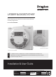
LP20RF & DIGISTAT+RF Radio frequency controlled room thermostat with dual channel programmer Part number RF562DR Spares Part number 31003 Spares Part number 22590DR ! For GREENSTAR CDi, GREENSTAR i JUNIOR and GREENSTAR Si MODELS also GREENSTAR i SYSTEM and GREENSTAR CDi SYSTEM MODEL(only when used with the optional integral diverter).
Support Sales: +44(0)845 1305522 Technical: +44(0)845 1307722 customer.care@draytoncontrols.co.uk www.draytoncontrols.co.uk @DraytonHeating /DraytonControls PLEASE READ THESE INSTRUCTIONS CAREFULLY BEFORE STARTING. These instructions are applicable to the Drayton model(s) stated on the front cover of this manual only and must not be used with any other make or model.
Table of contents Technical Data .............................................................................................................................. 2 Installation Guide .......................................................................................................... 3 LP20RF Installation ..................................................................................................... 4 Wireless Commissioning & Signal Strength.......................................................
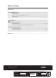
Technical Data Digistat+RF Transmitter Thermostat LP20RF Receiver Power supply 2xAA 1.5V alkaline batteries 24Vd.c. less than 65mA Radio frequency 433 MHz 433 MHz Radio signal range 30m typically. The range may be affected by the composition / density and number of walls between the Digistat+RF and LP20RF. Temperature setting range 5°C to 30°C Control Accuracy + 0.
Installation Guide 06515085001 ISSB LP20RF & DIGISTAT+RF 3 LP20RF & DIGISTAT+RF Client Drayton Artworker - Creative Director Mike Lane Modification Date 19/03/15 9:21AM File Name 7342 Drayton Amends LP20RF 06515085001 ISSB Proof Stage PRINT Finished Size A5 148x210mm Artwork % 100% Bleed 3mm
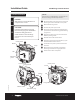
Installation Guide LP20RF Programmer & Receiver LP20RF Installation F ! NOTE: This accessory must be fitted by a competent person. Failure to comply could lead to prosecution. DANGER: 230 volts do not touch the electrical components or circuits. 1. CAUTION: 2. 3. 4. Isolate the mains electricity supply before starting any work and observe all relevant safety precautions. 5. Observe electro-static discharge precautions: do not touch the pcb circuit.
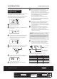
Installation Guide LP20RF & DIGISTAT+RF 9. Wireless Commissioning & Signal Strength Before fixing the Digistat+RF to the wall it is recommended to first check the signal strength from that location. To do this, after initial start up, the colon, CH and antenna symbols should be flashing on the LP20RF display. CLOCK? 1. 2. 3. OFF 5. 6. 10:30 PressCLOCK? the set? button 4 times; Lrn and OFF should be displayed. OFF CLOCK? 4.
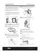
Installation Guide Positioning the Digistat +RF room thermostat LP20RF & DIGISTAT+RF 3. Replace the front by locating in position and pushing fully onto the back cover until the tab engages at the top of the transmitter. 4. Retighten the screw at the bottom of the unit to fully secure the front to the back cover. The Digistat is a radio frequency device which is very flexible for positioning as there is no need for hard wiring to the appliance.
Installation Guide LP20RF & DIGISTAT+RF Signal Strength Signal strength indicators To check signal strength on previously installed and paired units: 1. 2. 3. Transmitter code Signal strength indicators Press the ‘set’ button 4 times on the LP20RF. (may be different) Press ‘OK’ once. LED indicator shows different colour depending Press the ‘set’ button 5 times. The display will show ‘SSI and OFF’. Transmitter code (see table below) on signal strength (may be different) OFF OFF 4.
User Guide 06515085001 ISSB LP20RF & DIGISTAT+RF 8 Installation & User Guide
User Guide Digistat+RF Room Thermostat Digistat+RF Room Thermostat LCD Display º c An RF Model is shown by an antenna symbol on the display. Dial c º Set button Battery Compartment SET What is a room thermostat? A room thermostat simply switches the heating system on and off as necessary. It works by sensing the air temperature, switching on the heating when the air temperature falls below the thermostat setting, and switching it off once this set temperature has been reached.
User Guide Adjusting the Setpoint using the Preset Temperature Mode Change the temperature at the press of a button, for example, if you are going out to the shops for an hour you can reduce the temperature to save energy and then when you press the button again on your return the setpoint will return to the previous level. 1. You can either: 1.
User Guide Digistat+RF Room Thermostat Changing the Maximum Temperature Setting NOTE: When adjusting the settings within the menu, if the maximum or minimum possible setting are reached, the display will flash to indicate you cannot adjust the product further, e.g. you cannot set the Preset higher than the maximum temperature setting. 1.
User Guide Changing the Minimum Temperature Setting 1. To adjust the “Preset” temperature enter the User menu by pressing and holding the Set button for more than 5 but less than 10 seconds. The display will show ‘Pr’. Digistat+RF Room Thermostat Tamper Proofing To tamper proof the product i.e. prevent unauthorised adjustment of the product, set the Min. and Max. (HI and Lo) temperatures to the same desired value using the procedures above.
User Guide LP20RF Programmer & Receiver LP20RF Programmer & Receiver If the engineer has set your program and timings – you do not need to do anything else. Just keep this guide in a safe place for future reference. Introduction The programmer will automatically switch your central heating and hot water on and off at times that suit you. Central heating mode indicator Central heating modes: off = continuously off.
User Guide LP20RF Programmer & Receiver The Standard Program LP20RF NOTE: NOTE: The ON/OFF periods pre-programmed for Central Heating and Hot Water pre-heat are shown in the table below. These factory installed settings can be used without any further programming of the receiver. The time and date are pre-programmed and should not require adjustment. Two ON/OFF periods can be used instead of three, by setting the second ON/OFF periods to 12:00 as shown in the default program table.
PROG? User Guide LP20RF Programmer & Receiver PROG? 7. 8. Changing the Program Setting Central Heating (CH) MON - FRI 1. Press set? until SET and PROG? are shown in the display. MON TUE WED THU FRI PROG? Press + or - to change the OFF time. MON TUE WED THU FRI Press set? to set the OFF time and select the next PROG? ON time. MON TUE WED THU FRI8 to set the second and third CH Repeat operations 5 to PROG? ON/OFF times.
User Guide LP20RF Programmer & Receiver Setting individual weekdays: 5. 6. NOTE: If you do not require individual weekday times, then press set? until SET SAT-SUN are displayed and continue on the next page. If you do not wish to change the setting for the day displayed, then press set? until the first day you want to change is displayed. MON + TUEor WED THUchange FRI Press - to the OFF time. PROG? Press set? to set the OFF time and select the next MON TUE WED THU FRI ON time.
User Guide LP20RF Programmer & Receiver SAT SUN Setting Central Heating (CH) SAT - SUN: 1. 2. Repeat operations PROG?3 to 6 to set the second and third ON/OFF times. Press OK to select weekend. SAT SUN Press OK to select CH. NOTE: PROG? SUNthird CH OFF time, SET After pressing set? forSAT the PROG and HW for the weekend are displayed. SAT SUN 9:00 9:00 PROG PROG? 7. NOTE: Speed up the display by holding down the + or SAT SUN buttons. SAT SUN PROG? Press + or - to change the ON time.
SAT SUN User Guide PROG? LP20RF Programmer & Receiver SAT SUN PROG? Setting individual weekend days: Repeat operations 3 to 6 to set the second and third ON/OFF times. PROG? NOTE: If you do not require individual weekend day times, then press set? until the normal display is shown. 6:30 Setting Hot Water (HW) individual6:30 weekend days: 9:00 7. 9:00 NOTE: PROG? After pressing set? for the third CH OFF time, SET SAT displayed.
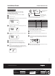
User Guide LP20RF Programmer & Receiver Setting holidays: 1. Setting the clock and time Press the set? button until SET and HDAY? are displayed. 1. Press the set? button until SET and CLOCK? are shown in the display. CLOCK? HDAY? 2. 3. 4. HDAY? Press OK and the display shows 00. 00 00 00 03 03 03 00 2. CLOCK? PressCLOCK? OK to display 24hr and ON. HDAY? CLOCK? 6:30 6:30 6:30 Press + or - to set the number of days you require the system to be off. HDAY? 3. 4.
8:08 DATE DATE User Guide DATE LP20RF Programmer & Receiver DATE Setting the date: 1. 8. Press the set? button until SET and DATE? are displayed. When the correct day has been chosen, press set? to select, now dLS will be displayed and ON will DATE flash. DATE ? DATE? 2. Press the OK button once, the year flashes on the DATE? display. DATE? DATE DATE? DATE 3. DATE 8:08 8:08 8:08 8:08 J DATE between ON or OFF.
Maintenance LP20RF & DIGISTAT+RF The Digistat +RF Room thermostat requires no maintenance. Digistat+RF Room thermostat part number 31003 The outer casing can be wiped clean using a dry cloth. DO NOT use polish or detergents. These units can not be serviced. Should the existing units fail to function correctly, check that the: ■■ LP20RF Receiver times and program settings are correct. ■■ RF signal link is set up (Refer to page 2 for RF signal range details).
Support Sales: +44(0)845 1305522 Technical: +44(0)845 1307722 customer.care@draytoncontrols.co.uk www.draytoncontrols.co.