“Dream Catcher” A 49' Grand Banks Classic Operating Manual Edition of March 27, 2013 Copyrighted. See notice next page.
Warning! This notice is a part of this manual, and is placed here to warn you as an owner, crew member or passenger on this vessel that the author of this manual assumes no responsibility for any errors or omissions herein, and represents only that the writings and illustrations herein represent his “best efforts” to provide a comprehensive overview of the vessel, so that it can be operated by a person who has the necessary experience and/or training to operate such a vessel given the additional information
Section 1: Introduction & General Boat Description 1A: About This Manual 1A1: Manual Objective and Limitations This manual is intended to introduce you to “Dream Catcher”, its systems, and features, allowing you to operate it with the confidence and self-assurance necessary to enjoy your cruising vacation to its fullest. It is not intended to replace a basic understanding of seamanship, including navigation skills, weather interpretation or boat handling.
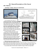
1B: General Description of this Vessel 1B1: Exterior Flybridge, Cockpit, Side & Forward Decks The Grand Banks 49' Classic is a traditional yacht design, with fiberglass hull, cabin, and flybridge structures, a teak swim step, teak decks, gunwale caps, and teak and stainless steel welded fittings and handrails. The windows, for the most part, are sliding glass panes. Of particular note are the easy walk-around decks, enabling safe, secure passage about the boat by the crew. A portion of the cockpit.
The aft cabin supports the dinghy on the starboard side. Tie-down straps hold the dinghy in place. The dinghy is lifted with an electric hoist from a strong davit with a windlass controlled by a plug-in remote control. Up five steps from the deck is the flybridge, with seating for crew and passengers in two tandem seats, each seating four passengers (for a total of eight); both have storage beneath. Within the port storage compartment is the galley propane tank and spare tank.
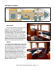
1B2: Salon & Helm Main Deck The boat is entered by side doors, port or starboard. These doors are fitted with deadbolt locks, and in addition have stainless catches affixed to the cabin sides to hold them open. The ”hold-open catches” should be engaged manually, not just by ”slamming the doors open” to avoid damage to the catches by bending, or the doors by banging. The doors should be closed when underway except at very low speeds in calm waters to avoid getting salt water inside.
Aft of the helm is a cabinet with a dry bar, drawer, locker, and an icemaker. The locker to right of the icemaker holds the flares, first aid kit, spotlight (with charging adapter) and davit control cable. Please feel free to Forward face of cabinet just aft of the salon helm. use what you need Note icemaker, cabinets and drawers. Wine cabinet is from this first aid kit. It in the top. is on the honor system. If you need it, use it.
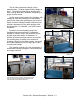
Galley: Forward of the port-side salon cabinet and settee is the galley. The galley has an propane stove/oven, a large stainless sink; a deepfreeze, a refrigerator; and a large microwave. There is extensive storage under and over the galley counters, and additional storage is under hatches in the #2 guest stateroom hold under the cabin floor. The compartment under the counter beneath the windshield on the port side forward of the stove is for dish storage.
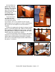
1B3: Passenger Accommodations Both the forward and aft cabins are down several steps below the salon. The VIP Guest and #2 Guest cabins and head compartment are forward, while the Master Stateroom and its head compartment is aft. Master Stateroom The aft (master) stateroom is down a few steps in the aft end of the salon. This master stateroom features a queen-sized island berth, beneath which are drawers including a spacious and efficient chart drawer.
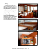
VIP Guest S/R All the way forward, the bow guest stateroom includes two large V-berths. Storage includes plenty of drawers, cabinets and hanging locker space for crew clothing. A large overhead hatch and side opening windows provide plenty of light and ventilation in this spacious cabin. When first The sumptuous forward V-Berth has a cushioned insert to getting acquainted with the boat, make it queen-sized plus.
1B4: Engine Room & Utility Room Preferred access to the engine room is through either the floor hatch by the helm seat in the salon leading directly to the Engine Room, or by going forward and lifting the stairs at the aft end of the companionway, which will lead you through the utility room first. AC and The salon floor engine room hatch. Note strap to hold it DC breakers in the ship’s open. You may prefer entering by the forward stairs.
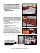
water. Mounted on the bulkhead itself are several battery main on-off switches for the starting and propulsion batteries, all clearly marked. Also on the wall under the table is the fuel manifold. At the aft end of each engine is its transmission, with the shafts exiting the hull through PSS dripless shaft seals. Morse control cables control the reverse gears. Alongside and inboard of each engine are the primary fuel filters.
1B5: Dinghy The boat is equipped with a 10 foot-6 inch Achilles tender which is a rigid-Hull, inflatable-pontoon boat and is fitted with a Yamaha 15hp four-cycle electric start outboard motor and portable fuel tank. Another view of Dreamcatcher’s dinghy.
1B8: Safety Equipment Anchors There is a permanently-rigged anchor on the bow pulpit and a spare anchor with an anchor rode in the lazarette Fire Extinguishers Handheld units are in the forward and aft stateroom, by the starboard salon door, and in the engine room. There is an automatic fixed system in the engine room, also fitted with a remote control on the aft face of the cabinet adjacent to the port salon door to the side deck. Engine room extinguisher remote activation control.
Section 2: Important Vessel Numbers Vessel Name: Dream Catcher Vessel Official Number: 699247 (This number is on the side of the hull in the port lazarette.
(Intentionally left blank) Section 2: Important Vessel Numbers 2.
Section 3: Checklists & Maneuvering Suggestions 3A: Operating Checklists - Dream Catcher First Thing Each Day 9 Check engine oil, coolant. 9 Check under-engine oil pads. Okay? Q Check fuel tank levels 9 Check holding tank indicators. Need pumping? 9 Turn off anchor light if illuminated. Starting Engines 9 All lines clear of propeller and on deck. 9 Items running on AC evaluated vis-a-vis the Inverter and Generator (page 4.13).
Arriving at Dock in Marina Q Lines secure, including spring lines. Q Step stool out, if needed. Q Water heater breaker off until Inverter current settles (see “Inverters” below). Q Shore power cord connected, AC Power Selector to “Shore”, Shore Power Selector to power cord location. Q Shore power confirmed on meter, Inverter “On”. Q Electric use monitored for current capacity of shore facilities. Arriving at Mooring Buoy Q Skipper puts starboard end of swim step, with mate on it, next to buoy.
3B: Maneuvering Suggestions 3B1: Docking & Undocking Because of its substantial weight, this boat is predictable! Take advantage of its momentum/inertia: you will find that if you maneuver slowly and thoughtfully you can maintain control at all times. Before undertaking docking in a "tight" space, practice with the boat in open but protected water to get the "feel" of the boat.
on the bow operating the anchor. Putting the bow of the boat over the spot where the anchor is to be placed after checking the depth on the depth sounder, the windlass foot-switches are used to lower the anchor slowly toward (but not onto) the bottom, by watching the chain markings.
3B4: Shore Lines When a shore line is required, anchors are set 75 - 100 feet from shore, with the boat backing toward shore during anchor-setting. The stern line is put around a tree, and brought back to the boat.
(Intentionally Left Blank) Section 3B: Maneuvering Suggestions 3.
Section 4: Specific Boat Systems & Operations This section of the operating manual will discuss each of the boat’s systems.
4A2: Anchor Chain Locker & Anchor Jams Anchor Handling: The anchor is forward on the bow pulpit, raised and lowered by the electric windlass. The chain goes then into the chain locker through the chain pipe behind the chain wheel (“wildcat”). From here, the chain goes into a compartment just forward of the bow locker. Be careful when using ths equipment! If a crew member is operating the windlass keep fingers, hands, arms, etc.
4A4: Anchor Windlass The anchor on Dream Catcher is raised and lowered by a Lofrans Tigres Windlass on the bow pulpit. The windlass is controlled by foot switches at the bow. The control circuit breaker for the windlass is on the windlass breaker panel on the starboard side of trhe salon helm console. The windlass raises/lowers the anchor. A large handwheel is the brake. If the windlass should fail to operate when its foot switches are Windlass panel by lower operated, trouble-shoot as follows: helm.
4B: Barbeque Dream Catcher carries a propane barbecue which mounts on the port side sundeck handrail near the steps from the port side deck. Its tank is nearby on the railing. To operate the barbecue: 1. Be sure the propane tank valve is on; 2. Turn the valve to the right of the grill to “High” 3. Press the igniter button or use a “propane match” to light the grill. 4C: Bilge Blowers The boat has bilge blowers controlled by “engine room fan” breakers in the AC panel at the lower helm.
4E: Dinghy, Davit & Outboard 4E1: Davit The boat uses its mast and boom to launch the Dinghy. This is expedited by an electric windlass that serves as the actual hoist. To use it: 1. Get the remote control from the low cabinet by icemaker in the salon. 2. Plug in the remote control to the receptacle under the The davit control socket is forward of the dinghy on the cabin wall. overhang by the mast above the sundeck; 3. Remove the tiedowns on the dinghy; 4.
4E2: Dinghy The dinghy aboard this boat is an 10'-6" Achilles hard-bottom inflatable boat. For safety, and compliance with U.S. rules, there should be a life jacket aboard the dinghy for each passenger aboard whenever the dinghy is at sea. Please be careful when pulling the dinghy ashore on beaches to minimize damage and scratches to the bottom. Dragging can be reduced by two persons if one is on each side. The dinghy in its chocks on the sundeck.
4F: Electrical Systems, AC 4F1: AC Generators The ship’s two Westerbeke generators provide 20,000 watts (“20KW Generator”) and 8,000 watts (“8KW Generator”) of AC power to the vessel and are used for battery charging, heating hot water, the washer/dryer, all air conditioning, and operation of incidental AC appliances. The generators are in the engine room.
Generator Exhausts: Each generator has an exhaust outlet just above the waterline midships under the aft spray rail. The 20KW generator exhausts to port, the 8KW to starboard. You will want to be careful with generator use when you have “rafted” Dream Catcher to another boat when anchored! Stopping a Generator: 1) Switch the Shore Power switch to “Off”. This 20 KW exhaust is on the port side... removes the load for the generator and allows it to cool down.
...It is also a Battery Charger, Making DC from AC! The Inverter can also do the reverse: If there is AC power available from a shore-side source or the generator, it can recharge the house batteries. The battery charger function receives that power through the “Inverter Battery Charger” breaker on the AC panel.
4F3: AC Breaker Panels Note: The electric panels must be photographed at an angle because their surface is so reflective. The nerve center of the AC electrical system are the AC circuit control panels by the wheel. Upper, “Breaker” Panel On the panel with the circuit breakers, just as in your home, some of these switches are true “circuit breakers”: they feed power to somewhere in the boat where there is another switch which, in turn, turns the item on and off.
“B”=Used as breaker “S”=Used as switch AND breaker ”*”=Also powered by the Inverter TOP AC PANEL (PANEL TO RIGHT OF LOWER HELM WHEEL) Breaker Use Breaker Use Left Side of Panel Circuit 1 Master 1 B Breaker for this entire side Fwd Cabin Aircon 1 S To compressor for forward cabin Aft Cabin Aircon 1 S To compressor for aft cabin Right Side of Panel Circuit 2 Master 2 S Beaker for this entire side Aircon Pump 2 S Turns on AC water pump. Must be on when using AC.
4F5: AC Power Selector Switches The lower AC panel to the right of the lower helm wall has three selector switches: “GENERATORS SELECTOR” This switch determines which generator is supplying power, if any... “AC POWER SELECTOR” This switch determines whether (1) the generator selected by the “Generators Selector” is supplying the boat, or (2) the shore power inlet selected by the “Shore Power Selector is supplying the boat...
circuits — to be sure you have not overloaded the circuit. Important Note: If the house batteries are low when you first hook up to shore power, and the inverter is turned on (as it should be), the inverter will begin charging its batteries at a very high charging rate, drawing a lot of shore power current. Until this demand reduces (see “The Inverter System” below), you should turn “OFF” other high-current AC appliances such as the water heater. You can then turn on AC appliances as needed.
4G: Electrical Systems, DC 4G1: DC Concepts Each year it seems more folks are confused by the operation of electrical systems on yachts than by any other subject! Don’t feel discouraged if something isn’t clear: you’ve got company in your confusion. So let’s try to cover some theory here first. Most of the equipment on any boat is run by 12-volt DC electricity from the boat’s batteries.
4G2: DC Batteries The batteries on this boat are not just one, big all-purpose battery. To have redundancy, there are actually several “banks” of batteries assigned different tasks. A “starting bank” is used for starting engines. This battery is charged by the engine alternator when running, or by the McCarron battery charger if it is on when there is shore power or a generator is running. Another “house bank” consists of deep cycle batteries wired in parallel.
4G4: DC Battery “On-Off” Switch This switch is the DC circuit master switch for the house service. It should be left “on” at all times unless there is a fire or short circuit, and you wish to cut off electric power to all DC voltage except the starting circuits. 4G5: DC Circuit Breaker Panels The nerve center of the DC electrical system is the DC circuit breaker panels just right of the lower helm. On these panel are the switches that control power to the boat’s various systems.
DC Upper (Main) Breaker Panel: DC UPPER PANEL PANEL (TO LEFT OF SALON DOOR) BREAKER USE BREAKER LEFT COLUMN USE CENTER RIGHT COLUMN Port Engine S Powers port engine & its instruments Starting Port & Starboard S Press to start the engine Engine Vent S Turns on port engine room blower Stopping Port & Starboard S Press to sto eng. (SOL must be ON) Stbd Engine S Powers stbd engine & its instruments Bilge Pump Mode Sws. S Control B.P.
4G6: DC Voltmeter In the DC Breaker Panel is a voltmeter with a battery selector switch. When the photo was taken, the switch was in the “house” position, and the meter showed 13.2 volts. As the scale indicates, around 11.0 volts (red) is considered “dead”; 12.8 volts (100%) is a fully-charged, unused battery; 13.2 volts is a battery getting a “float” charge to keep it charged; 14.2 volts is a battery being “bulk” charged.
4H: Electronics The boat is equipped with extensive electronic equipment, including VHF radios, Radars, GPS, Plotter; Depth Sounder; Speed Log; Autopilot; and Navigation Computer. Each unit is provided with a dedicated or shared circuit breaker in the DC power panel; this breaker must be on for the unit to be used. Then the unit’s own power button must have been depressed or its knob must be also be in the “ON” mode. (The computer runs on 110volt AC from shore power or the inverter.
4H2: Electronics: Depth Sounder & Knotmeter/Log - Datamarine There is a Datamarine digital depth sounder and speed log system on the flybridge, with repeaters at the lower helm, showing depth BELOW THE KEEL and speed in knots, trip mileage in nautical miles, etc. Operation of this system is described in its operating manual, but it is quite simple and intuitive. They are turned on by the breaker in the DC power panel.
4H4: Electronics: GPS Receivers Dream Catcher has two Furuno GPS receivers, one at each helm. See the manuals for operating details. 4H5: Electronics: Hailer The boat is equipped with a loudhailer at the flybridge for communicating with the shore. It also can be used to talk from the helm to the flybridge. It operates conventionally, but is seldom used. It also has foghorn and bell modes for lying at anchor or operating in fog. This manual is stored on the laptop: “Documents|LH-10 Loudhaler”.
4H7: Electronics: Stereo In the salon in the aft cabinet by the settee “L” is a Pioneer Stereo AM/FM receiver, with an iPod connection in the adjacent top drawer. This is like an automobile unit. The “Front/Rear” speaker control (fader) shifts the sound among the boat’s speakers as noted on the placard. 4H8: Electronics: Radar & AIS The boat is equipped with two radar sets, one at each the flybridge and the lower helm.
4J: Engine & Transmissions 4J1: General Discussion The main engines on the boat are Caterpillar 3208-T Diesels producing a maximum of 320 horsepower each. These extraordinarily-reliable, rugged machines are top-of-the-line, and can be expected to give you trouble-free, economical cruising. Each engine is controlled at the lower helm DC Panel with a stop breaker (common to both engines), its own power breaker, and its start and stop buttons; the engine's instruments are on the helm panels at both helms.
Check the Coolant Level. The heat exchanger coolant tanks are located forward of each engine. Be sure coolant is at or above the “Low-Add” line when cold. If coolant is needed, determine if there is any sign of a coolant leak under the engine, and if there is, do not run the engine; if no leak, add coolant from the jug of pre-mixed antifreeze/corrosion inhibitor/water supplied on the boat.
4J4: Engine Operating Parameters The following parameters are estimated based upon parameters from Caterpillar. RPM Speed Fuel Consumption Naut. Miles/Gallon 1200 6.0 Knots 3.5 GPH 1.72 1500 7.5 5.0 GPH 1.50 1800 10.0 8.5 GPH 1.17 2000 10.5 12.0 GPH .88 2400 11.5 16.5 GPH .70 4J5: Engine Synchronizer The Glendinning Synchronizer located in the engine room overhead automatically, exactly synchronizes the engine speeds.
4J6: Engine Transmissions Check the Transmission Oil Level Check the oil level once every two weeks, more often if a transmission shifts erratically. It is unlikely that any oil will need to be added. Be sure to check under the transmission for leaks! Low transmission oil is a serious matter. The red arrows point to the starboard dipstick & fill. With the engine idling, remove the Arrow points to transmission fill and dipstick location. transmission dipstick. Wipe it, reinsert it, and take a reading.
4K: Fresh & Waste Water Systems 4K1: Fresh Water Fill Location There are two water tanks filled by fills on the side decks (labeled “WATER”). Do not overfill the water tanks, lest you damage the vent filters. Stop filling as soon as you hear the water coming up the tank standpipe. Be sure to use the "water" fills, not the "waste" deck fittings! 4K2: Fresh Water Heater After the water pump, water is distributed directly to the cold water faucet lines. In addition, it goes to the boat's water heater.
4L: Fuel System 4L1: Fuel System Concept The Diesel fuel aboard Dream Catcher is carried in two side tanks of 500 gallons each. This gives the boat great cruising range. As long as both engines are operating, fuel consumption should be fairly uniform, and the boat should stay “in trim”. If it doesn’t, you can reduce consumption from either tank by operating the control valves — although they normally should all be simply left open! The fuel valves are under the engine room workbench.
4L4: Fuel Management In the aft end of the engine room there are sight gauges on just forward of each tank that let you see the level in each. To use, you must open the valve on the top and bottom of each gauge tube. Be sure to close both valves after use! They protect the boat in the event a sight gauge breaks! There also is a fuel manifold consisting of a set of valves for the fuel supply to the main engines, generators, and Diesel furnace.
4M1: Air Conditioning Operation The boat is equipped with an electric Cruisair Air Conditioning and Heating System including four compressors. Its outlets are located throughout the boat controlled by a thermostats throughout the boat. Breakers in the AC Breaker Panel at the lower helm must be on for operation of the system. This panel is the main control station for the A/C system.
The furnace is controlled by a master switch on the port side of the lower helm cabinet, and by thermostats in each area. The master switch has three settings: Off The heating system is “all off” System Heat The Diesel Furnace will supply heat if called for by any thermostat Engine Heat The port engine (if running) will supply heat if called for by any thermostat Select the desired master switch setting and then set the desired temperature on the thermostats.
fenders or get too close while rafting due to the very high temperature of the exhaust gases from the furnace. See illustration on preceding page. Furnace Blower Controls “Fan Heater” controls are located throughout the boat in areas where there are no thermostats. These will supply heat to that area when the switch is on “Low” or “High” and the furnace is running. Furnace Thermostats See illustration on preceding page.
4N: Galley & Appliances Dream Catcher is fitted with a number of appliances for your convenience. Most of these (like the microwave) are easy to operate, “just like a home appliance”; nevertheless, we will spend some time discussing these, as marine units have some features that are slightly different than home models. 4N1: Barbecue The barbecue is mounted atop the sundeck hand rail. Its propane tank is nearby. It operates conventionally.
There is, of course, a manual gas valve on the propane tank. This valve is used only when exchanging/filling tanks. There is also a second valve, a “solenoid valve”, in the flybridge seat propane line immediately after the manual valve. This electric valve is controlled by a switch in the galley, and in this way the cook can actually shut off the propane supply to the stove at its source when it not being used.
Note: The oven burner will not immediately light! For safety reasons, the control has a slight time delay, and the oven’s main burner will light after about 20 or 30 seconds following control-setting. In this way, the burner does not “puff” on and off as you adjust the control.
4P: Head Systems 4P1: Overview The head system on this boat is reliable, straightforward, and easy-to-use. First, a note about discharge of sewage: It is forbidden to discharge untreated sewage in inland US. waters, an area that includes all US. waters in which this boat operates. The boat holding tank must only be emptied at proper pump-out stations if it is in US. waters. (This rule does not apply in Canadian waters.
4P3: Head Problems The only likely head problem is a clogged head or a full holding tank. Use the other one... Remember, the two head systems are completely separate: If you have trouble, turn off the faulty head and use just the other head; call NWE for assistance. Of course, if a holding tank is full, that head cannot work; in this case, the toilet has a “shutdown relay” and stops operating! Pump the holding tank (see below) when required! 4P3: Holding Tank There are two 35-gallon holding tanks.
There are overboard valves in the lines where the discharge hoses connect to the through-hills. These should be open, too. Section 4P: Head Systems 4.
4Q: Running Gear 4Q1: Shaft Seals The vessel is equipped with a PSS dripless shaft seals that are lubricated by water from the engine; the seals should be occasionally checked by the owner to be sure that there is not inappropriate water leakage. Adjustment should be rarely required. Section 4Q: Running Gear 4.
4R: Safety Equipment 4R1: Safety - Equipment Listing This vessel is equipped with complete safety equipment, detailed on page 1.12 4R2: Safety - Fire Suppression System Automatic extinguisher pilot light. If lit, it is armed & ready. The boat has a fire suppression system built in to the engine room. It is manually operated, and the vessel operator pulls the control to operate it.
4S: Sea Strainers & Through-Hulls 4S1: Sea Strainer Cleaning and Seacocks The sea strainers on this boat are secure and reliable. They protect the engine, generator and refrigeration cooling systems from water-borne debris which might block internal equipment passages. If a sea strainer needs cleaning (see above regarding inspection) here is the procedure: 1. Look at the base of the strainer near the hull. On one side may be a welded-bar “wing nut”.
(Intentionally left blank) Section 4T: Warning Lights, Alarms, Wipers 4.
Section 5: “What to Do If” for Some Specific Concerns 5A: ANCHOR CHAIN WON’T COME OUT OF CHAIN LOCKER The anchor chain is continuous, secured at both ends, and cannot tangle. But sometimes a pile of chain will fall over, and one loop of chain will fall through another loop.
one was closed, re-prime engine or call a mechanic if you can’t do this (see Caterpillar engine manual). 5G: HEAD WON’T FLUSH Is breaker on? Turn it on. Have you over-filled the holding tank? Pump it to allow more effluent to enter it. See the “Heads” section of this manual. If all else fails, just use only the other head. 5H: HIT A FISH NET Engines in Neutral: don’t try to back off, you may foul the net more. Try pulling the boat back with the dinghy & outboard. Get assistance from the fisherman.
Section 6: Emergency Procedures 6A: PROTECT YOUR LIVES FIRST... Put on life jackets Contact the Coast Guard with an emergency "MAYDAY" call. If adrift, prepare to anchor to keep the boat from drifting into danger. If the boat is really sinking, consider "beaching it" if necessary. Launch the dinghy and prepare to board if necessary. Take a handheld VHF radio, if available. Be sure to wear life jackets! 6B: ...
6D: HITTING A LOG, ROCK, OR DEBRIS ----- PLEASE DON’T! Hitting a log is a real risk in our Northern waters because logging, and "log rafts," are such a big part of our commerce. If you hit a log: - Did you put a hole in the boat? Idle the engine, then think: usually, you can tell just by where the noise of the hit came from. Check the bilges (don't forget the lazarette area, where the rudder posts are) after putting the engine into idle and/or neutral, if necessary.
Section 7: Index AC.. . . . . . . . 1-2, 1-1-1-12, 2-1, 3-1-3-5, 4-1-4-17, 4-19-4-25, 4-27-4-37, 4-40, 4-41, 5-1, 5-2, 6-1, 6-2 AC Power Panel. . . . . . . . . . . . . . . . . . . . . . . . . . . . . . . . . . . . . . . . . . . . . . . . . . . . . . . . . . . . . . . . . 4-7 Accommodations. . . . . . . . . . . . . . . . . . . . . . . . . . . . . . . . . . . . . . . . . . . . . . . . . . . . . . . . . . . . . . . . 1-7 Air Conditioning.. . . . . . . . . . . . . . . . . . . . . . . . . . . . . . . . . . . .
Fire Extinguishers. . . . . . . . . . . . . . . . . . . . . . . . . . . . . . . . . . . . . . . . . . . . . . . . . . . . . . . . . . . . . . . 1-12 Flares. . . . . . . . . . . . . . . . . . . . . . . . . . . . . . . . . . . . . . . . . . . . . . . . . . . . . . . . . . . . . . . . . . . . 1-5, 1-12 Flashlight. . . . . . . . . . . . . . . . . . . . . . . . . . . . . . . . . . . . . . . . . . . . . . . . . . . . . . . . . . . . . . 1-7, 1-8, 4-24 Flybridge. . . . . . . . . . . . . . . . . . . . . . . . . . .
Propeller. . . . . . . . . . . . . . . . . . . . . . . . . . . . . . . . . . . . . . . . . . . . . . . . . . . . . . . . . . . . . . . . . . . 3-1, 5-2 Pump. . . . . . . . . . 1-9, 4-4, 4-6, 4-8, 4-11, 4-16, 4-17, 4-24, 4-27-4-29, 4-36, 4-37, 4-40, 4-41, 5-1, 5-2 Radar. . . . . . . . . . . . . . . . . . . . . . . . . . . . . . . . . . . . . . . . . . . . . . . . . . . . . . . . . . . . 1-3, 1-4, 4-17, 4-22 Radio. . . . . . . . . . . . . . . . . . . . . . . . . . . . . . . . . . . . . . . . . . . . . . . . .