
User Guide


HY13-1518-M1/USA
Low Speed High Torque, Hydraulic Motors
TK Series
Parker Hannifin Corporation
Hydraulic Pump/Motor Division
Greeneville, TN 37745 USA
Hydraulics
25
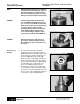
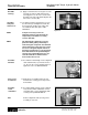
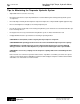
Assemble
wear plate
and rotor set
13. Assemble wear plate (10) with rotor set over
the drive link (11) and alignment studs onto
the housing (21) and the rotor splines into
mesh with the drive link splines. SEE
FIGURE 37.
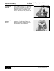
Assemble
seal ring
12. Apply a small amount of clean grease to new
seal rings (5) and assemble them into the
seal ring grooves on the rotor set side of the
wear plate (10) and on the manifold plate side
of the rotor set stator (9B).
NOTE It may be necessary to turn one
alignment stud out of the housing (21)
temporarily to assemble rotor set (9)
over the drive link.
Figure 37
Torqmotor Assembly
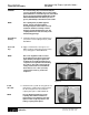
NOTE The manifold (6) is made up of several
plates bonded together permanently to
form an integral component. The manifold
surface that must contact the rotor set has
it’s series of irregular shaped cavities on
the largest circumference or circle around
the inside diameter. The polished impres-
sion left on the manifold by the rotor set
is another indication of which surface
must contact the rotor set.
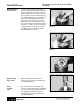
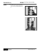
Assemble
seal &
commutator
Note
19. Assemble a new seal ring (3) into commuta-
tor (4) and assemble commutator over the
end of drive link (11) onto manifold (6) with
seal ring side up. SEE FIGURE 39.
Remove alignment studs (if used) prior to
assembly of end cover.
Figure 39
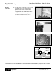
Assemble
manifold
16. Assemble the manifold (6) over the alignment
studs and drive link (11) and onto the rotor
set. Be sure the correct manifold surface is
against the rotor set. SEE FIGURE 38.
Insert a seal
in manifold
17. Apply grease to a new seal ring (5) and
insert it in the seal ring groove exposed on
the manifold.
Figure 38