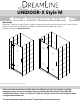
UNIDOOR-X Style M Glass-to-glass hinge shower door installation IMPORTANT DreamLine® reserves the right to alter, modify or redesign products at any time without prior notice. For the latest up-to-date technical drawings, manuals or additional details please refer to your model’s web page on DreamLine.com Right Hand Door installation shown Please read these instructions carefully before installing.
Model Numbers UNIDOOR X Style M with 6” hinge panel D12372-## D12472-## D12572-## D12672-## D12772-## D12872-## D12972-## D13072-## UNIDOOR X Style M with 24” hinge panel with Left or Right L-Bracket D32372L-## D32372R-## D32472L-## D32472R-## D32572L-## D32572R-## D32672L-## D32672R-## D32772L-## D32772R-## D32872L-## D32872R-## D32972L-## D32972R-## D33072L-## D33072R-## ##- hardware finish 01- Chrome 04- Brushed Nickel 06- Oil Rubbed Bronze UNIDOOR-X Style M Ver 1 Rev 5 03/2016 2
Used with the following Model Styles: Style L1 Style M1 Style M3 Style M5 UNIDOOR-X Style M Ver 1 Rev 5 03/2016 Style M Style M2 Style M4 Style M6 3
STYLE L1 * UNIDOOR-X Shower door 23”~30” with 6” or 24” hinge panel and with 30”- 34” full height return panel secured using u-channel STYLE M * UNIDOOR-X Shower door 23”~30” with 6” or 24” hinge panel secured using u-channel STYLE M1 * UNIDOOR-X Shower door 23”~30” with 6” or 24” hinge panel and with 6”, 6-1/2”, 14”, 14-1/2”, 22” or 22-1/2” full height inline panel secured using u-channel STYLE M2 * UNIDOOR-X Shower door 23”~30” with 6” or 24” hinge panel with 12”, 18”, 24” or 26” inline buttress panel
Preparation 1. Prior to installation, examine all boxes and packages for shipping damage and compare the piece count with your packing slip. After opening all boxes and packages read this introduction carefully. Check that all of the needed parts are included in the package by checking off the components on the “Detailed Diagram of Shower Door Components”.
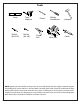
Tools Level Drill bit (Ø=5/16") Tape Measure Drill bit (Ø=1/8") Pencil Power Drill Phillips Screwdriver Miter saw Hammer Caulk NOTE: Unpack your unit carefully and inspect it. Lay it out and identify all parts using the detailed diagram and packing list in your manual as a reference. Before discarding the carton, check for small hardware bags that may have fallen to the bottom of the box. If any parts are damaged or missing, please contact DreamLineTM for replacement.
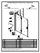
Detailed Diagram of shower door components Left hand L-Bracket (shown) 9 Right hand L-Bracket 35 32 13 1 23 34 2 33 5 7 29 8 Packing List 01 02 05 07 08 09 Glass door Handle Hinge Bottom anti-water strip L-shaped strip * U-channel 1 (76”, wall profile) 1pc 1pc 2pcs 1pc 1pc 1pc 1pc 13 23 29 32 33 34 35 Ø5/16” Wall anchor Countersunk screw ST4.2x40 U-channel 2 (44”, bottom profile) Hinge panel glass (6” or 24”)*** Flanged anti-water strip PVC glass spacer (0.
Installation steps Style “M” 6” & 24” In-Line Panel and Shower Door Installation NOTE: The following shower door installation instructions should be used as a general guide and prerequisite to the installation of the UNIDOOR Style M, M1, M2, M3, M4 and L1 models. Before you begin the installation, please check your finished opening size and model dimensions to ensure proper placement of the Hinge panel glass (#32) and Glass door (#01). Specific size information can be found on our website at: www.
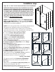
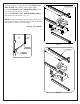
3. Remove both U-channels from the Hinge Panel Glass 2 (#32) and carefully set the glass aside. Cut the U-channel 1 (76”, wall profile) (#09) at the top mark that was shown in Fig. 2.1 Cut the U-channel 2 (44”, bottom profile) (#29) at the mark that was shown in Fig. 2.2 U-Channel 1 L NOTE: It may be necessary to remove any burrs from the cut end of the U-channels with a metal file before placing the U-channel onto the glass. See Fig. 2 for details Fig 2.1 U-Channel 2 L Fig 2.
1 4. Position the U-channel 2 (bottom profile) (#29) onto the threshold along your line and mark the position of the holes for drilling. You need to use at least 3 holes for the U-channel 2 (bottom profile) (#29): one near each end and one near the center. • Drill the holes into the threshold using an 1/8” Ø drill bit. • Apply a bead of silicone to the bottom of the U-channel 2 (bottom profile) (#29) and attach it to the threshold using the ST4.2 x 40mm screws (#23).
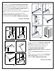
6. Apply good quality mildew resistant silicone into both u-channels. • Add the Adjustment spacers (#34) from step#2 into to the bottom u-channel (Fig 5) • Install the Hinge Panel glass (#32) into U-channel 2 (#29) (bottom profile) and the U-channel 1 (#09) (wall profile). Apply silicone to the exposed end of the U-channel (Fig. 6). See Fig.
7. The L-Bracket (#35) is not included with the 6” hinge 1 2 3 4 panel installation. If you are installing the 6” hinge panel glass (#32), it is strongly recommended to allow the silicone to fully cure before hanging the door glass. If you are installing the 24” hinge panel glass (#32), continue onto step #8 for the installation of the L-Bracket (#35). See Fig.
L- Bracket Assembly Parts List 35.9 35.4 35.5 35.3 35.6 35.2 35.1 35.7 35.8 35.1 35.2 35.3 35.4 35.5 PVC spacer Rubber tip set screw L-Bracket (left hand shown) Decorative cover Ø5/16” Wall anchor UNIDOOR-X Style M Ver 1 Rev 5 03/2016 1 pc 2 pcs 1 pc 1 pc 6 pcs 35.6 35.7 35.8 35.9 Wall plate Truss Head Screw ST 4.
Left hand bracket installation 1 8. Install the L-Bracket assembly (#35) as shown. 3 2 See Fig. 8 & 9 for details NOTE: The left hand L- bracket installation is shown. Follow the same steps if you are installaing the right hand L-bracket.
9. Attach the Hinges (05) to the Stationary glass 2 (32) with the decorative bolts facing inside the shower. Place a piece of 5/8” thick flat wood or a spacer of equal thickness on the threshold or shower base next to the Stationary glass 2. Place the Glass door (01) on the wood or spacer to ensure that the door height is at 72”. Level up the Glass door next to the Stationary glass panel and fasten the hinges onto the Glass Door using one gasket per side.
11. Measure the bottom of the Glass door (#01) from end to end to determine the actual width of the door. Cut the Bottom anti-water strip (#07) to the size of your measurement and notch 3/8” of the inner side of the Bottom anti-water strip (#07)as shown in Fig 12 Press the Bottom Anti-water strip (#07) onto the bottom edge of the Glass door (#01). Handle side of door NOTE: Make sure the Bottom anti-water strip (#07) is flush to the vertical edge of the Handle side of the Glass door (#01).
For Style M only: If your model does not include additional panel glass, procede to install the L-shaped strip (#08) to the wall for the door to close against to seal. 1 ATTENTION: Prior to the next step, please be sure that the section of the wall where you need to attach the L-shaped strip (#08) is clean, dry and free from soap, oil and any construction debris. 13. With the door closed place the L-shaped strip (#08) on the door edge and mark its location on the wall.
14. With the door open apply waterproof silicone along the connection of both U-Channels to the wall and threshold on the inside of shower. NOTE: The surface needs to be clean and free of debris before applying silicone. Let the silicone cure before closing the door to avoid contact with the bottom Flanged anti-water strip (#33). See Fig. 15 for details Fig 15 15. Allow 24 hours for the silicone to fully cure before using the shower.
Product Maintenance BASES and BACKWALLS: To ensure long lasting life for your acrylic back walls: wipe them off after each use with a soft cloth. To clean the acrylic back walls use non-abrasive sprays or cream based cleaners. Avoid the use of aerosol spray cleaners. Never use abrasive cleansers, metal brushes or scrapers that could scratch or dull the surface. GLASS: To ensure long lasting life for your glass shower products: wipe them off after each use with a soft cloth.
TEL: 866-731-2244 FAX: 866-857-3638 DREAMLINE.COM For more information on DreamLine® Shower Doors and Enclosures please visit DreamLine.