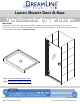
Lumen Shower Door & Base SHOWER DOOR AND BASE INSTALLATION INSTRUCTIONS IMPORTANT DreamLine® reserves the right to alter, modify or redesign products at any time without prior notice. For the latest up-to-date technical drawings, manuals, warranty information or additional details please refer to your model’s web page on DreamLine.
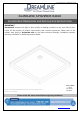
©2018 DreamLine. All Rights Reserved SLIMLINE SHOWER BASE SHOWER BASE DIMENSIONS AND INSTALLATION INSTRUCTIONS IMPORTANT DreamLine® reserves the right to alter, modify or redesign products at any time without prior notice for the purpose of product improvement and customer experience. Please refer to the model’s web page on DreamLine.com for the latest technical drawings, installation manuals, warranty information or additional product details.
©2018 DreamLine. All Rights Reserved Preparation 1. Prior to installation, examine all boxes and packages for shipping damage and compare the piece count with your packing slip. After opening all boxes and packages read this introduction carefully. Check that all of the parts are included in the package by checking off the components on the parts list.
©2018 DreamLine.
©2018 DreamLine.
©2018 DreamLine.
©2018 DreamLine.
©2018 DreamLine.
©2018 DreamLine.
©2018 DreamLine.
©2018 DreamLine.
©2018 DreamLine.
©2018 DreamLine.
©2018 DreamLine. All Rights Reserved Shower Base Cross Section Diagram Finished Wall Shower Base Cement board (2"×4") Stud Mortar Drain* * not included This product should be installed by someone familiar with the construction requirements for this type of project and the care necessary for the safe installation and operation of the product.
©2018 DreamLine. All Rights Reserved Shower Base Installation - Preparation 1. Ensure that the floor and the studs are at right angles. Provide a 5”×5” opening in the subfloor for the drain. The 2” PVC waste pipe should extend above the surface of the sub-floor according to the drain installation instructions and the height of the Shower base. Refer to the product drawings and tables in this installation manual for the drain location.
©2018 DreamLine. All Rights Reserved 2. Install the shower drain (NOT INCLUDED) according to the drain installation manual (supplied with the drain). (Fig 2) Fig 2 3. Place the tray into the designated position so that the Drain cutout drops around the Drain Pipe and butt the Shower Base up against the studs. (Fig 3) Lower the base over the drain pipe and set it into place against the studs.
©2018 DreamLine. All Rights Reserved 4. Level the tray and place marks on the studs above the upper edge of the tile flange. (Fig 4) Level base in two directions Fig 4 5. Mix the bedding material (Mortar, cement-sand mix, etc.) Concrete or plaster is not recommended. Apply enough bedding material to support the entire bottom of the shower base. This will add additional stability and prevent the base from shifting position.
©2018 DreamLine. All Rights Reserved 6. After the bedding material has been poured and before it sets, place the shower base into the position with the drain assembly sliding over the PVC waste pipe. It will be necessary to push the shower base until the top of the tile flange aligns with the marks drawn on the studs and the front edge is contacting the rough floor along the entire length of the shower base. Ensure that the base is level in all directions.
©2018 DreamLine.
©2018 DreamLine. All Rights Reserved Product Maintenance BASES and BACKWALLS: To ensure long lasting life for your acrylic base and/or back walls: wipe them off after each use with a soft cloth. To clean the acrylic base or back walls use non-abrasive sprays or cream-based cleaners. Avoid the use of aerosol spray cleaners. Never use abrasive cleansers, metal brushes or scrapers that could scratch or dull the surface.
TEL: 866-731-2244 FAX: 866-857-3638 DREAMLINE.COM For more information on DreamLine® Shower Doors and Enclosures please visit DreamLine.com ©2018 DreamLine.
LUMEN SHOWER DOOR INSTALLATION INSTRUCTIONS d e rve n i L e s m e a R e Dr ghts © Ri All IMPORTANT DreamLine® reserves the right to alter, modify or redesign products at any time without prior notice for the purpose of product improvement and customer experience. Please refer to the model’s web page on DreamLine.com for the latest technical drawings, installation manuals, warranty information or additional product details.
Table of Contents Page # Section title Model Diagram 2 Preparation 3 Tools Parts List Installation Steps Handle Vinyl Seals Hinge Assembly Detail Product maintenance d e v e r n i L e s m e a R e Dr ghts © Ri All 4 5-6 7-18 17 17 19 20 d e e in serv L m Re a e Dr ghts © Ri All ! This product should be installed by someone familiar with the construction requirements for this type of project and the care necessary for the safe installation and operation of the product.
Model Diagram d e e n v i ser L m e a R e Dr ghts © Ri All Left-Swing door installation Right-Swing door installation ! ©2018 DreamLine. All Rights Reserved d e e n v i ser L m e a R e Dr ghts © Ri All NOTE: This model is reversible for left or right door swing installation. This manual will use the left door swing installation as an example throughout. For a right door swing installation, simply begin on the opposite wall and reverse the orientation of the parts as necessary.
Preparation 1. Prior to installation, examine all boxes and packages for shipping damage and compare the piece count with the packing slip. After opening all boxes and packages read this introduction carefully. Check that all of the necessary parts are included in the package by checking off the components on the “Detailed Diagram of Shower Door Components”.
Tools Level Tape Measure Drill bit Ø5/16" (8mm) Pencil d e e n v i ser L m e a R e Dr ghts © Ri All Silicone Hammer Power Drill Razor Knife Painter’s Tape 1/2” Shims Phillips Screwdiver Work Gloves Tip: Measure the finished opening before Drill bit Ø=1/8" (3.2mm) Hex Head driver 2mm, 4mm Safety glasses Top proceeding with the installation to be sure that the correct model size has been ordered.
Detailed Diagram of shower door components 13 14 15 1 3 2 d e e n v i ser L m 6 e a R Dre ghts TOP OF DOO 7 © Ri R GL ASS 5 l l A 4 16 17 8 9 10 11 18 ©2018 DreamLine.
Parts List 01 02 03 04 05 06 DESCRIPTION QTY Wall Profile 1pc Hinge Profile 1pc d e e n v i (pre-installed) r L e Hinge Side Vinyl Seal s m e a R e Hinge Assembly ts Dr gh(pre-installed) ©Pivot Bushing i (pre-installed) R l l A Door Glass 1pc 2pcs 4pcs 1pc 07 Strike Rail 1pc 08 Magnet Strip (pre-installed in #07 and #09) 2pcs 09 Strike Profile 1pc 10 Wall Profile 1pc 11 Handle 1pc 12 Sweep Vinyl Seal 1pc 13 ST4.
Installation steps 1. Meaure the finished opening width at the top (at model height), middle and bottom. Check the threshold for level and the walls for plumb. (Fig 1) d e e n v i ser L m e a R e Dr ghts © Ri All ! Note that this model can adjust up to 1/2” per side for out-of-plumb conditions or 1” for overall width within the model size. Threshold must be level Measure the finished opening Fig 1 2. Install the Wall Profile (hinge side) (#01) first.
3. Apply silicone to the back of the Wall Profile (hinge side) (#01). Attach the Wall Profile (hinge side) (#01) to the wall using the ST4.2x 40 Truss Head Screws (#15). (Fig 3a) 15(x4) 1 d e e n v i ser L 2 m e a R e Dr ghts © Ri All ST4.2x40 Fig 3a ! NOTE: There is a top and a bottom to the door glass. The handle holes are closer to the top. (Fig 3b) 5-13/16” (148mm) TOP OF DOOR GLASS d e e n v i ser L m e a R e Dr ghts © Ri All 5-1/4” (134mm) ©2018 DreamLine.
4. Slide the Hinge Profile (#02) assembly fully into the Wall Profile (#01). (Fig 4) 1 2 d e e n v i ser L m e a R e Dr ghts © Ri All Fig 4a d e e n v i ser L m e a R e Dr ghts © Ri All ©2018 DreamLine. All Rights Reserved ! NOTE: It is very important to protect the bottom edge of the door glass during installation. Use 1/2” shims on the threshold for proper spacing and to support the door during the next few steps.
! 1 DO NOT REMOVE THE TWO SMALLER HINGE BOLTS: Only loosen these smaller bolts enough to allow the door glass to slide into the hinge. remove the large bolts and sleeves 5. The Hinge Assemblies (#04) are pre-attached to the Hinge Profile (#02). Remove the large allen bolts and protective sleeves from the hinges. (Fig 5.1) Loosen the smaller allen bolts on the hinges to create enough space to slide the glass into the hinges. *Place the protective sleeves into the hinge holes on the Door Glass (#06).
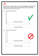
7a. Adjust the strike and hinge profiles within the wall profiles to center the door within the model size range. DO NOT adjust either profile more than 1/2”. The ID groove on the hinge profile and strike profile should not be visible. DO NOT over adjust the profiles beyond the ID groove .
7b. Check the door for level. Adjust the Hinge Profile (#02) as necessary. From inside of the shower, drill an Ø1/8” hole through the predrilled hole at the top of the hinge-side Wall Profile (#01) and secure the Wall Profile (#01) to the hinge profile using an ST4.2 x 10mm Pan Head Screw (#13) and Washer (#14). This will provide some support for the door until the remaining ST4.2 x 10mm (#13) screws are installed in Step #12, after the Strike side profiles are installed.
9. Open the door and remove the Strike Profile (#09) and leave the Wall Profile (#10) in position. Mark the holes for drilling through the holes in the Wall Profile (#10). Drill Ø5/16”(8mm) holes and insert the Wall Anchors (#16) into the holes. Apply silicone to the back of the Wall Profile (#10) and around the screw holes. Attach the Wall Profile (#10) to the wall using the ST4.2x 40 Truss Head Screws (#15).
10. Insert the Strike Profile (#09) back into the installed Wall Profile (#10), and adjust the Strike Profile (#09) as necessary to line up the magnetic seals. (Fig 10) 1 d e e n v i ser L m e a R e Dr ghts © Ri All d e e n v i ser L m e a R e Dr ghts © Ri All LUMEN shower door manual Ver 1 Rev 2 09/2018 ©2018 DreamLine.
11. The Strike Rail (#07) magnet on the Door Glass (#06) must line up with the magnet on the Strike Profile (#09). Make sure the magnets make even contact from top to bottom. (Fig 11) d e e n v i ser L m e a R e Dr ghts © Ri Magnet strips All inside door outside of shower Top view of strike-side wall profile ©2018 DreamLine.
12. Adjust the door for level and plumb by adjusting the profiles on either side of the door. Use the pre-drilled holes on the inside of the Wall Profiles (#01 and #10) as guides. After making final adjustments to the Door Glass (#06), drill holes into the Hinge Profile (#02) and Strike Profile (#09) through the pre-drilled holes in the Wall Profiles (#01 and #10) using an Ø1/8” (3.2mm) drill bit. NOTE: Drill through one layer of the profile, not through the entire profile.
13. Install the Handle (#11) onto the Door Glass (#06) using the ST4.2x10 Pan Head Screws (#13) and one gasket per side to prevent glass to metal contact. Cover the handle screws with the decorative caps. (Fig 13) doo cap s scre ws r d e e n v i ser L m e a R e Dr ghts © Ri All slee gas ves ket ins i ha de nd le gas ket ou t ha side nd le Fig 13 14. Notch the strike end of the Bottom Strip (#12) with a razor knife to fit around the Strike Rail (#07) on the edge of the Door Glass (#06).
15. From inside the shower, apply a good quality mildew-resistant silicone where the profiles meet the walls. Silicone may also be applied on the outside of the profiles if necessary. (Fig 15) NOTE: The surfaces need to be clean and free of debris before applying silicone. ! Allow 24 hours for the silicone to cure before using the shower. d e e n v i ser L m e a R e Dr ghts © Ri All 24 Hours de d ne sig by an Bri Lie ©2018 DreamLine.
Hinge Assembly Detail ! FOR REFERENCE ONLY! It is NOT necessary to fully disassemble the hinges during installation! Hinge Back Plate Countersunk Allen Screw M4x16 d e e n v i ser L m e a R e Dr ghts © Ri All Countersunk Allen Screw M6x20 Lorem ipsum M6 Screw Cap Hinge Front Plate Gasket Ø10mm Plastic Sleeve Pivot Pins Pivot Bushing d e e n v i ser L m e a R e Dr ghts © Ri All LUMEN shower door manual Ver 1 Rev 2 09/2018 ©2018 DreamLine.
Product Maintenance BASES and BACKWALLS: To ensure long lasting life for your acrylic back walls: wipe them off after each use with a soft cloth. To clean the acrylic back walls use non-abrasive sprays or cream based cleaners. Avoid the use of aerosol spray cleaners. Never use abrasive cleansers, metal brushes or scrapers that could scratch or dull the surface.
d e e n v i ser L m e a R e Dr ghts © Ri All d e e n v i ser L m e a R e Dr ghts © Ri All TEL: 866-731-2244 FAX: 866-857-3638 DREAMLINE.COM For more information on DreamLine® Shower Doors and Enclosures please visit DreamLine.com ©2018 DreamLine.