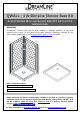
QWALL – 4 & SlimLine Shower Base Kit ACRYLIC SHOWER WALL AND SHOWER BASE KIT INSTALLATION INSTRUCTIONS IMPORTANT DreamLineTM reserves the right to alter, modify or redesign products at any time without prior notice. For the latest up-to-date technical drawings, manuals or any other details please refer to the support.BathAuthority.com web page.
QWALL – 4 ACRYLIC SHOWER WALL INSTALLATION INSTRUCTIONS IMPORTANT DreamLineTM reserves the right to alter, modify or redesign products at any time without prior notice. For the latest up-to-date technical drawings, manuals or any other details please refer to the support.BathAuthority.com web page. Please read these instructions carefully before installing.
Preparation 1. After opening all boxes and packages, read this introduction carefully. Check that all of the needed parts are included in the package, by marking all the components on the “Detailed Diagram of Shower Door Components”. Examine boxes and packages for shipping damage. If the unit has been damaged, has a finishing defect, or has missing parts, please contact our customer support department within 5 business days of the delivery date.
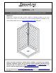
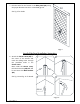
Detailed Diagram of Acrylic Shower Wall Components 2 1 3 4 5 6 7 8 Packing List 01 Side panel 2pcs 05 Glass shelf 2pcs 02 Corner cover 1pc 06 Wall anchor 11pcs 03 Decorative edge molding 2pcs 07 Countersunk screw ST4.2×30 11pcs 04 Shelf bracket 6pcs 08 Decorative cover 5pcs NOTE: Unpack your unit carefully and inspect it. Lay it out and identify all parts using the detailed diagram and packing list in your manual as a reference.
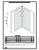
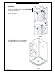
Preparation for Installation of Side Panel ATTENTION: If you are installing a shower enclosure with a wall profile, you can hide the edge of the Side panel (01) behind the wall profile. Side Panel 1 Wall Profile Wall See Fig. 1 for details. Side Panel 2 Wall Profile Wall Fig. 1 1. Place a mark on the walls with a distance of 1” (one inch) from the corner and draw a plumb vertical line from top to bottom. See Fig. 2 for details. 1 2 1" 1" Fig. 2 Ver. 1, Rev.
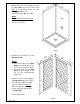
2. Measure the walls of the shower from the 1” (one inch) line in the corner (from Step. 1) to the points where you want Side panels (01) to end. The distances are “D1” and “D2”. D1 D2 D1 NOTE: “D2” Shows wall with the fixture. See Fig. 3 for details. Fig. 3 3. Determine the position of both Side panels (01). NOTE: a) The narrow edge of the Side panels fits behind the corner cover and cannot be trimmed. b) The wide edge of the Side panel can be trimmed to the size of your measurements from step 2.
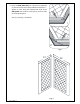
4. Place the Side panel (01) on a flat piece of plywood or particle board. Use a sharp industrial knife and a Tsquare to score along the marked wide ends of the Side panel and continue scoring until you have fully cut through the panel. See Fig. 5 and Fig. 6 for details. 1 2 Fig. 5 D1 D2 Fig. 6 Ver. 1, Rev.
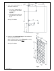
5. Take exact measurements of the fixture on the wall: • • 1" D2 A from the 1” (one inch) line in the corner of the shower to the fixture: (A, B, C) from the bottom of the wall of the shower to the fixture: (E, F). See Fig. 7 for details. C E B F Fig. 7 6. Determine which Side panel (01) will be installed on the side wall with the fixture. Mark the fixture location on the Side panel according to the measurements taken in Step. 5. A D2 See Fig. 8 for details. E F B C Fig. 8 Ver. 1, Rev.
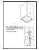
7. Drill the holes for the fixtures in the Side panel (01) using the proper diameter saw bit or a handheld jig saw. D2 See Fig. 9 for details. Fig. 9 Acrylic Side Panel Installation Instruction 8. Attach the Corner cover (02) to the corner of the shower and mark the drilling holes through the predrilled holes in the Corner cover. Move aside the Corner cover, Drill the holes using Ø5/16” drill bit and insert the Wall Anchors (06). See Fig. 10 and Fig. 11 for details. 1 2 3 4 Ø5/16" Fig. 10 Ver.
Fig. 11 9. Mount the Corner cover (02) to the corner of the shower using the Countersunk screws ST4.2×30 (07). Do not fully tighten the screws at this time; leave them loose for further installation. 1 See Fig. 12 and Fig. 13 for details 2 Fig. 12 Ver. 1, Rev.
Fig. 13 10. Apply the sealant to the entire surface of the reverse side of the Side panel (01). Also, apply the sealant around the drilled holes. See Fig. 14 for details. Fig. 14 Ver. 1, Rev.
11. Slide the narrow edge of the Side panel (01) behind the Corner cover (02). Align trimmed edge of the Side panel (from Step. 4) with the marked line on the wall (in Step. 2) and push the Side panel against the wall. NOTE: Make sure the drilled holes on the Side panel are also aligned with the fixtures on the wall. 1 2 See Fig. 15 for details. Fig. 15 12. Apply sealant to the entire surface of the reverse side of the other Side panel (01). See Fig. 14 for details. 1 13.
14. Once Side panels (01) aligned, fasten tight the Corner cover (02) to secure the Side panels. Cover the screw holes with the Decorative cover (08). 1 See Fig. 17 for details. 2 Fig. 17 ATTENTION; Prior to the next step, please be sure the part of the wall for installation of the Decorative edge molding (03) is clean, dry and free from soap, oil and any construction debris. 15.
16. Apply caulk along the top edge of the Side panels (01) and along the connection of the bottom edges of the Side panels with the Shower base. See Fig. 19 for details. ATTENTION: Installation of “QWALL-4” Acrylic shower wall is complete. If you want to install Glass shelves (05) to your Shower, follow to the next step. Fig. 19 Glass Shelves Installation Instruction 17. Determine the desired height for the Glass shelves (05) and mark the locations on the wall.
18. Mark the location for the Shelf brackets (04) according to the measurements in Fig. 20 and Fig. 21.1. Drill the holes using Ø5/16” drill bit and insert the Wall anchors (06). See Fig. 21 for details. 3 1/2" 3 1/2" 3 1/2" 1 Ø 5/16" 2 3 Fig. 21 1 19. Mount the Shelf brackets (04) to the wall using the Countersunk screws ST4.2×30 (07). NOTE: the padded set screw of the Glass bracket should be facing down.
Fig. 23 Product maintenance To insure long lasting life for your acrylic back walls, wipe them off after each use with a soft cloth. To clean the acrylic back walls use non-abrasive sprays or cream based cleaners. Never use abrasive cleansers, metal brushes or scrapers that could scratch or dull the surface. Acrylic cleaning procedure: Acrylic should be cleaned with warm water and a clean, nonabrasive cloth. If desired, a mild, nonabrasive detergent may also be used.
SLIMLINE SHOWER BASE SHOWER BASE DIMENSIONS AND INSTALLATION INSTRUCTIONS IMPORTANT DreamLineTM reserves the right to alter, modify or redesign products at any time without prior notice. For the latest up-to-date technical drawings, manuals or any other details please refer to your model’s web page on BathAuthority.com Please read these instructions carefully before installing.
Preparation 1. Prior to installation, examine all boxes and packages for shipping damage and compare the piece count with your packing slip. After opening all boxes and packages, read this introduction carefully. Check that all of the needed parts are included in the package by checking off the components on the “Detailed Diagram of Shower Door Components”.
SINGLE THRESHOLD SHOWER BASE Center Drain Configuration W W1 11 D1 D MODEL SPECIFICATION D (in) W (in) D1 (in) W1 (in) DLT-1132320 DLT-1136360 32"×32" 36"×36" 32" 36" 32" 36" 15" 15" 16" 18" DLT-1134420 34” x 42” 34” 42” 15” 21” DLT-1132480 DLT-1136480 DLT-1130600 DLT-1132600 DLT-1134600 DLT-1136600 32"×48" 36"×48" 30"×60" 32"×60" 34"×60" 36"×60" 32” 36" 30" 32" 34" 36" 48” 48" 60" 60" 60" 60" 15” 15" 15" 15" 15" 15" 24” 24" 30" 30" 30" 30" “SLIMLINE SHOWER BASE” Ver.5 Rev.
SINGLE THRESHOLD SHOWER BASE Left-Hand Drain Configuration W W1 D1 D MODEL SPECIFICATION D (in) W (in) D1 (in) W1 (in) DLT-1130601 DLT-1132601 DLT-1134601 DLT-1136601 30"×60" 32"×60" 34"×60" 36"×60" 30" 32" 34" 36" 60" 60" 60" 60" 15" 15" 17" 18" 12" 12" 12" 12" “SLIMLINE SHOWER BASE” Ver.5 Rev.
SINGLE THRESHOLD SHOWER BASE Right-Hand Drain Configuration W W1 D1 D MODEL SPECIFICATION D (in) W (in) D1 (in) W1 (in) DLT-1130602 DLT-1132602 DLT-1134602 DLT-1136602 30"×60" 32"×60" 34"×60" 36"×60" 30" 32" 34" 36" 60" 60" 60" 60" 15" 15" 17" 18" 12" 12" 12" 12" “SLIMLINE SHOWER BASE” Ver.5 Rev.
NEO ANGLE SHOWER BASE W C C A W B A MODEL SPECIFICATION W (in) A (in) B (in) C (in) DLT-2036360 DLT-2038380 DLT-2040400 DLT-2042420 36"×36" 38"×38" 40"×40" 42"×42" 36" 38" 40" 42" 18 5/16" 20 5/16" 22 5/16" 24 5/16" 25" 25" 25" 25" 12" 12" 14 3/8" 14 3/8" “SLIMLINE SHOWER BASE” Ver.5 Rev.
QUARTER ROUND SHOWER BASE W C C W R MODEL SPECIFICATION W (in) C (in) R (in) DLT-7033330 DLT-7036360 DLT-7038380 33"×33" 36"×36" 38"×38" 33" 36" 38" 12" 12" 12" 21 5/8" 21 5/8" 21 5/8" “SLIMLINE SHOWER BASE” Ver.5 Rev.
DOUBLE THRESHOLD SHOWER BASE Corner Drain Configuration W C C W MODEL SPECIFICATION W (in) C (in) DLT-1032320 DLT-1036360 32"×32" 36"×36" 32" 36" 12" 12" “SLIMLINE SHOWER BASE” Ver.5 Rev.
DOUBLE THRESHOLD SHOWER BASE Left-Hand Drain Configuration W W1 D1 D MODEL SPECIFICATION D (in) W (in) D1 (in) W1 (in) DLT-1034481 DLT-1036481 DLT-1036601 34"×48" 36"×48" 36"×60" 34" 36" 36" 48" 48" 60" 17" 18" 18" 12" 12" 12" “SLIMLINE SHOWER BASE” Ver.5 Rev.
DOUBLE THRESHOLD SHOWER BASE Right-Hand Drain Configuration W W1 D1 D MODEL SPECIFICATION D (in) W (in) D1 (in) W1 (in) DLT-1034482 DLT-1036482 DLT-1036602 34"×48" 36"×48" 36"×60" 34" 36" 36" 48" 48" 60" 17" 18" 18" 12" 12" 12" “SLIMLINE SHOWER BASE” Ver.5 Rev.
Shower Base Cross Section Diagram Shower Base Cement board Finished Wall (2"×4") Stud Mortar Drain “SLIMLINE SHOWER BASE” Ver.5 Rev.
Shower Base Installation - Preparation 1. Ensure that the floor and the studs are at right angles. Provide a 5”×5” opening in the subfloor for the drain. The 2” PVC waste pipe should extend above the surface of the sub-floor according to the drain installation instructions and the height of the Shower base. Refer to the product drawings and tables in these installation instructions for the drain location. 90° 90° 90° See Fig. 1 and Fig. 2 for details.
2. Install the shower drain (NOT INCLUDED) according to the drain installation manual (supplied with the drain). See Fig. 3 for example Fig. 3 3. Place the tray into the designated position so that the Drain Body drops around the Drain Pipe and butt the Shower Base up against the studs. See Fig. 4 for details. Lower the base over the drain pipe and set it into place against the studs. Fig. 4 “SLIMLINE SHOWER BASE” Ver.5 Rev.
4. Level the tray and place marks on the studs above the upper edge of the tile flange. See Fig. 5 for details. Level base in two directions Fig. 5 5. Mix the bedding material (Mortar, cement-sand mix, etc.) Concrete or plaster is not recommended. Apply enough bedding material to support the entire bottom of the shower base. This will add additional stability and prevent the base from shifting position. See Fig. 6 for details. Mortar Fig. 6 “SLIMLINE SHOWER BASE” Ver.5 Rev.
6. After the bedding material has been poured and before it sets, place the shower base into the position with the drain assembly sliding over the PVC waste pipe. It will be necessary to push the shower base until the top of the tile flange aligns with the marks drawn on the studs and the front edge is contacting the rough floor along the entire length of the shower base. Ensure that the base is level in all directions.
Fig. 9 Product maintenance To ensure long lasting life for your acrylic back walls, wipe them off after each use with a soft cloth. To clean the acrylic back walls use non-abrasive sprays or cream based cleaners. Never use abrasive cleansers, metal brushes or scrapers that could scratch or dull the surface. To ensure long lasting life for your glass shower products, wipe them off after each use with a soft cloth. Rinse and wipe of the glass using either soft cloth or squeegee to prevent soap buildup.
DREAMLINE™ EXCLUSIVE LIMITED WARRANTY AS OF MAY 6, 2013 This warranty extends only to the original owner/end‐user for household use only and is not transferable to a subsequent owner. This warranty extends for a designated period of time, so long as it remains in use in its original place of installation. This warranty applies only to DreamLine products purchased from an authorized dealer in United States or Canada.
TEL: 866-731-2244 FAX: 866-857-3638 WWW.BATHAUTHORITY.COM For more information on DreamLineTM Shower Bases please visit www.BathAuthority.