Visions Shower Door & Base SHOWER DOOR & BASE INSTALLATION INSTRUCTIONS IMPORTANT DreamLine® reserves the right to alter, modify or redesign products at any time without prior notice. For the latest up-to-date technical drawings, manuals, warranty information or additional details please refer to your model’s web page on DreamLine.
SLIMLINE SHOWER BASE SHOWER BASE DIMENSIONS AND INSTALLATION INSTRUCTIONS IMPORTANT DreamLine® reserves the right to alter, modify or redesign products at any time without prior notice. For the latest up-to-date technical drawings, manuals, warranty information or additional details please refer to your model’s web page on DreamLine.com Color options: --- - White -22- Biscuit -88- Black ® For more information about DreamLine products please visit DreamLine.
Preparation 1. Prior to installation, examine all boxes and packages for shipping damage and compare the piece count with your packing slip. After opening all boxes and packages read this introduction carefully. Check that all of the needed parts are included in the package by checking off the components on the “Detailed Diagram of Shower Door Components”.
SINGLE THRESHOLD SHOWER BASE Center Drain Configuration W W1 11 D1 D MODEL DLT-1132320 DLT-1136360 SPECIFICATION 32"× 32" 36"× 36" D (in) 32" 36" W (in) 32" 36" D1 (in) 15" 15" W1 (in) 16" 18" DLT-1132420 32” x 42” 32” 42” 15” 21” DLT-1134420 34” x 42” 34” 42” 15” 21” DLT-1136420 36” x 42” 36” 42” 15” 21” DLT-1142420 42” x 42” 42” 42” 20” 21” DLT-1132480 DLT-1134480 DLT-1136480 DLT-1132540 DLT-1130600 DLT-1132600 DLT-1134600 DLT-1136600 32"× 48" 34” x 48” 36"× 48" 32” x 54”
SINGLE THRESHOLD SHOWER BASE Left-Hand Drain Configuration W W1 D1 D MODEL SPECIFICATION D (in) W (in) D1 (in) W1 (in) DLT-1130601 DLT-1132601 DLT-1134601 DLT-1136601 30"×60" 32"×60" 34"×60" 36"×60" 30" 32" 34" 36" 60" 60" 60" 60" 15" 15" 17" 18" 12" 12" 12" 12" SLIMLINE SHOWER BASE manual Ver 5 Rev 8 07/2017 4
SINGLE THRESHOLD SHOWER BASE Right-Hand Drain Configuration W W1 D1 D MODEL SPECIFICATION D (in) W (in) D1 (in) W1 (in) DLT-1130602 DLT-1132602 DLT-1134602 DLT-1136602 30"×60" 32"×60" 34"×60" 36"×60" 30" 32" 34" 36" 60" 60" 60" 60" 15" 15" 17" 18" 12" 12" 12" 12" SLIMLINE SHOWER BASE manual Ver 5 Rev 8 07/2017 5
NEO ANGLE SHOWER BASE W C C A W B A MODEL SPECIFICATION W (in) A (in) B (in) C (in) DLT-2036360 DLT-2038380 DLT-2040400 DLT-2042420 36"×36" 38"×38" 40"×40" 42"×42" 36" 38" 40" 42" 18 5/16" 20 5/16" 22 5/16" 24 5/16" 25" 25" 25" 25" 12" 12" 14 3/8" 14 3/8" SLIMLINE SHOWER BASE manual Ver 5 Rev 8 07/2017 6
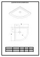
QUARTER ROUND SHOWER BASE W C C W R MODEL SPECIFICATION W (in) C (in) R (in) DLT-7033330 DLT-7036360 DLT-7038380 33"×33" 36"×36" 38"×38" 33" 36" 38" 12" 12" 12" 21 5/8" 21 5/8" 21 5/8" SLIMLINE SHOWER BASE manual Ver 5 Rev 8 07/2017 7
DOUBLE THRESHOLD SHOWER BASE Corner Drain Configuration W C C W MODEL SPECIFICATION W (in) C (in) DLT-1032320 DLT-1036360 32"×32" 36"×36" 32" 36" 12" 12" SLIMLINE SHOWER BASE manual Ver 5 Rev 8 07/2017 8
DOUBLE THRESHOLD SHOWER BASE Left-Hand Drain Configuration W W1 D1 D MODEL SPECIFICATION D (in) W (in) D1 (in) W1 (in) DLT-1034481 DLT-1036481 DLT-1036601 34"×48" 36"×48" 36"×60" 34" 36" 36" 48" 48" 60" 17" 18" 18" 12" 12" 12" SLIMLINE SHOWER BASE manual Ver 5 Rev 8 07/2017 9
DOUBLE THRESHOLD SHOWER BASE Right-Hand Drain Configuration W W1 D1 D MODEL SPECIFICATION D (in) W (in) D1 (in) W1 (in) DLT-1034482 DLT-1036482 DLT-1036602 34"×48" 36"×48" 36"×60" 34" 36" 36" 48" 48" 60" 17" 18" 18" 12" 12" 12" SLIMLINE SHOWER BASE manual Ver 5 Rev 8 07/2017 10
Shower Base Cross Section Diagram Finished Wall Shower Base Cement board (2"×4") Stud Mortar Drain* * not included SLIMLINE SHOWER BASE manual Ver 5 Rev 8 07/2017 11
Shower Base Installation - Preparation 1. Ensure that the floor and the studs are at right angles. Provide a 5”×5” opening in the subfloor for the drain. The 2” PVC waste pipe should extend above the surface of the sub-floor according to the drain installation instructions and the height of the Shower base. Refer to the product drawings and tables in this installation manual for the drain location. 90° 90° 90° See Fig. 1 and Fig. 2 for details.
2. Install the shower drain (NOT INCLUDED) according to the drain installation manual (supplied with the drain). See Fig. 3 for example Fig. 3 3. Place the tray into the designated position so that the Drain cutout drops around the Drain Pipe and butt the Shower Base up against the studs. See Fig. 4 for details. Lower the base over the drain pipe and set it into place against the studs. Fig.
4. Level the tray and place marks on the studs above the upper edge of the tile flange. See Fig. 5 for details. Level base in two directions Fig. 5 5. Mix the bedding material (Mortar, cement-sand mix, etc.) Concrete or plaster is not recommended. Apply enough bedding material to support the entire bottom of the shower base. This will add additional stability and prevent the base from shifting position. See Fig. 6 for details. Mortar Fig.
6. After the bedding material has been poured and before it sets, place the shower base into the position with the drain assembly sliding over the PVC waste pipe. It will be necessary to push the shower base until the top of the tile flange aligns with the marks drawn on the studs and the front edge is contacting the rough floor along the entire length of the shower base. Ensure that the base is level in all directions.
Fig.
Product Maintenance BASES and BACKWALLS: To ensure long lasting life for your acrylic base and/or back walls: wipe them off after each use with a soft cloth. To clean the acrylic base or back walls use non-abrasive sprays or cream based cleaners. Avoid the use of aerosol spray cleaners. Never use abrasive cleansers, metal brushes or scrapers that could scratch or dull the surface. GLASS: To ensure long lasting life for your glass shower products: wipe them off after each use with a soft cloth.
TEL: 866-731-2244 FAX: 866-857-3638 DREAMLINE.COM For more information on DreamLine® Shower Doors and Enclosures please visit DreamLine.
VISIONS SHOWER DOOR & TUB DOOR INSTALLATION INSTRUCTIONS IMPORTANT DreamLineTM reserves the right to alter, modify or redesign products at any time without prior notice. For the latest up-to-date technical drawings, manuals or any other details please refer to your model’s web page on BathAuthority.com Please read these instructions carefully before installing.
Preparation 1. Prior to installation, examine all boxes and packages for shipping damage and compare the piece count with your packing slip. After opening all boxes and packages read this introduction carefully. Check that all of the needed parts are included in the package by checking off the components on the “Detailed Diagram of Shower Door Components”.
Detailed Diagram of Shower Door Components 10 9 8 7 3 2 1 11 12 5 13 4 14 6 15 16 17 Packing List 01 02 03 04 05 06 07 08 09 Glass profile Wall profile Guide rail Glass door Stationary glass Handle Magnetic strip Anti-water strip Single side strip 2pcs 2pcs 2pcs 2pcs 2pcs 2pairs 1pair 4pcs 2pcs 10 11 12 13 14 15 16 17 Round head screw ST4.2×30 Round head screw ST4.2x25 Round head screw ST4.2x10 Flat head screw ST4.
Shower Door Installation 1. Measure the distance between the two finished walls at the top, middle and bottom. This distance is marked as “W”. Also check the threshold for level and the walls for plumb. See Fig. 1 for details. W Fig. 1 2. Your Guide rails (#03) have been precut for the model width of: 60”. (the rails are shorter than the model width by design). If W is less than 60" (W<60”), then you will need to cut the Guide rails (#03) equally from both ends.
Fig. 3 3. Once the Guide rails (#03) have been cut, you will need to reinstall the roller stoppers on each Guide rail (#03) on both ends. It is important that these stoppers are installed at the correct location. Remove the existing stopper. Mark the drilling hole at a distance of 2” from the cut off end of the Guide rail (#03). Drill a new hole using an Ø 1/8” drill bit; then re-attach the stopper with the screw.
4. Fasten the bottom Guide rail (#03) to the Glass profiles (#01) with the Round head screws ST4.2x25 (#11). See Fig. 5 for details. TIP: For ease of assembly, add some liquid soap or wax to lubricate the screws prior to attaching the glass profiles to the guide rails. Also, use a low setting on your power drill to prevent stripping the screws during assembly. Fig. 5 5.
6. Install the Single side strips (#09) in-between the Stationary glass (#05) and the Glass profiles (#01). The strips should be inserted on the side that is facing the inside of the shower. (See detail in Fig. 7) ATTENTION: Do not use a screwdriver or other metal objects to install the Single Side Strip; you can scratch or damage the glass and aluminum. inside 7.
9. Move the finished frame to the designated position on the shower base, the bathtub or the threshold (depending on your installation); push it against the walls. If your top and bottom wall opening measurements vary or if the walls are out-of-plumb, make adjustments by sliding the Wall profiles (#02) out of the Glass Profiles (#01). Use a level to adjust the frame so that it is plumb. See Fig. 9 for details. Fig. 9 10.
12. Fasten the top and the bottom Wheel assemblies (#17) to the Glass doors (#04). The top wheels can adjust the door level with the adjustable bolt and lock nut. The bottom wheel has a press button to fix the wheel on to the bottom Guide rail (#03). Note: The lock nut of the upper wheel and the press button of the bottom wheel should be pointing up. (Fig 11.1 and 11.2) 1 4 2 5 3 6 See Fig. 11 for details. Fig. 11 13. Slide the top door wheels into the top Guide rail (#03).
14. Install the Handles (#06) to the Glass doors (#04).(Fig 13.1) Press the anti-water strips (#08) o n t o t h e v e r t i c a l e d g e s o f t h e Stationary glass (#05) and both vertical edges of the Glass doors (#04). Press the Magnetic strips (#07) onto the vertical edges of both Glass doors (#04) for a tight seal. See Fig. 13 for details. 1 2 3 Fig. 13 15. Do the final adjustments of the assembled unit in the Wall profiles (#02). Make sure that the bottom rail is tight to the the threshold.
16. Apply a good quality mildew resistant silicone along the profiles and guide rails; on the seams between the bottom guide rail and the profiles as well as along the shower base or threshold. See Fig. 15 for details. Caulk Fig. 15 Product Maintenance BASES and BACKWALLS: To ensure a long life for your acrylic back walls: wipe them off after each use with a soft cloth. To clean the acrylic back walls use non-abrasive sprays or cream based cleaners.
TEL: 866-731-2244 FAX: 866-857-3638 WWW.BATHAUTHORITY.COM For more information on DreamLineTM Shower Doors & Tub Doors please visit www.BathAuthority.