VISIONS SHOWER DOOR & BASE INSTALLATION INSTRUCTIONS Wall Profile with Flange STEP 1: Shower Base Installation Instructions OR STEP 2: Shower Door Installation Instructions ! CHOOSE the APPROPRIATE MANUAL for your model version Wall Profile without Flange Wall Profile WITH Flange: VISIONS Manual Ver 1 Rev 7 072015 OR Wall Profile WITHOUT Flange: VISIONS Manual Ver 2 082018 For more information about DreamLine® products please visit DreamLine.
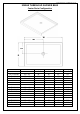
©2018 DreamLine. All Rights Reserved SLIMLINE SHOWER BASE SHOWER BASE DIMENSIONS AND INSTALLATION INSTRUCTIONS IMPORTANT DreamLine® reserves the right to alter, modify or redesign products at any time without prior notice for the purpose of product improvement and customer experience. Please refer to the model’s web page on DreamLine.com for the latest technical drawings, installation manuals, warranty information or additional product details.
©2018 DreamLine. All Rights Reserved Preparation 1. Prior to installation, examine all boxes and packages for shipping damage and compare the piece count with your packing slip. After opening all boxes and packages read this introduction carefully. Check that all of the parts are included in the package by checking off the components on the parts list.
©2018 DreamLine.
©2018 DreamLine.
©2018 DreamLine.
©2018 DreamLine.
©2018 DreamLine.
©2018 DreamLine.
©2018 DreamLine.
©2018 DreamLine.
©2018 DreamLine.
©2018 DreamLine.
©2018 DreamLine. All Rights Reserved Shower Base Cross Section Diagram Finished Wall Shower Base Cement board (2"×4") Stud Mortar Drain* * not included This product should be installed by someone familiar with the construction requirements for this type of project and the care necessary for the safe installation and operation of the product.
©2018 DreamLine. All Rights Reserved Shower Base Installation - Preparation 1. Ensure that the floor and the studs are at right angles. Provide a 5”×5” opening in the subfloor for the drain. The 2” PVC waste pipe should extend above the surface of the sub-floor according to the drain installation instructions and the height of the Shower base. Refer to the product drawings and tables in this installation manual for the drain location.
©2018 DreamLine. All Rights Reserved 2. Install the shower drain (NOT INCLUDED) according to the drain installation manual (supplied with the drain). (Fig 2) Fig 2 3. Place the tray into the designated position so that the Drain cutout drops around the Drain Pipe and butt the Shower Base up against the studs. (Fig 3) Lower the base over the drain pipe and set it into place against the studs.
©2018 DreamLine. All Rights Reserved 4. Level the tray and place marks on the studs above the upper edge of the tile flange. (Fig 4) Level base in two directions Fig 4 5. Mix the bedding material (Mortar, cement-sand mix, etc.) Concrete or plaster is not recommended. Apply enough bedding material to support the entire bottom of the shower base. This will add additional stability and prevent the base from shifting position.
©2018 DreamLine. All Rights Reserved 6. After the bedding material has been poured and before it sets, place the shower base into the position with the drain assembly sliding over the PVC waste pipe. It will be necessary to push the shower base until the top of the tile flange aligns with the marks drawn on the studs and the front edge is contacting the rough floor along the entire length of the shower base. Ensure that the base is level in all directions.
©2018 DreamLine.
©2018 DreamLine. All Rights Reserved Product Maintenance BASES and BACKWALLS: To ensure long lasting life for your acrylic base and/or back walls: wipe them off after each use with a soft cloth. To clean the acrylic base or back walls use non-abrasive sprays or cream-based cleaners. Avoid the use of aerosol spray cleaners. Never use abrasive cleansers, metal brushes or scrapers that could scratch or dull the surface.
TEL: 866-731-2244 FAX: 866-857-3638 DREAMLINE.COM For more information on DreamLine® Shower Doors and Enclosures please visit DreamLine.com ©2018 DreamLine.
VISIONS SHOWER DOOR & TUB DOOR INSTALLATION INSTRUCTIONS IMPORTANT DreamLineTM reserves the right to alter, modify or redesign products at any time without prior notice. For the latest up-to-date technical drawings, manuals or any other details please refer to your model’s web page on BathAuthority.com Please read these instructions carefully before installing.
Preparation 1. Prior to installation, examine all boxes and packages for shipping damage and compare the piece count with your packing slip. After opening all boxes and packages read this introduction carefully. Check that all of the needed parts are included in the package by checking off the components on the “Detailed Diagram of Shower Door Components”.
Detailed Diagram of Shower Door Components 10 9 8 7 3 2 1 11 12 5 13 4 14 6 15 16 17 Packing List 01 02 03 04 05 06 07 08 09 Glass profile Wall profile Guide rail Glass door Stationary glass Handle Magnetic strip Anti-water strip Single side strip 2pcs 2pcs 2pcs 2pcs 2pcs 2pairs 1pair 4pcs 2pcs 10 11 12 13 14 15 16 17 Round head screw ST4.2×30 Round head screw ST4.2x25 Round head screw ST4.2x10 Flat head screw ST4.
Shower Door Installation 1. Measure the distance between the two finished walls at the top, middle and bottom. This distance is marked as “W”. Also check the threshold for level and the walls for plumb. See Fig. 1 for details. W Fig. 1 2. Your Guide rails (#03) have been precut for the model width of: 60”. (the rails are shorter than the model width by design). If W is less than 60" (W<60”), then you will need to cut the Guide rails (#03) equally from both ends.
Fig. 3 3. Once the Guide rails (#03) have been cut, you will need to reinstall the roller stoppers on each Guide rail (#03) on both ends. It is important that these stoppers are installed at the correct location. Remove the existing stopper. Mark the drilling hole at a distance of 2” from the cut off end of the Guide rail (#03). Drill a new hole using an Ø 1/8” drill bit; then re-attach the stopper with the screw.
4. Fasten the bottom Guide rail (#03) to the Glass profiles (#01) with the Round head screws ST4.2x25 (#11). See Fig. 5 for details. TIP: For ease of assembly, add some liquid soap or wax to lubricate the screws prior to attaching the glass profiles to the guide rails. Also, use a low setting on your power drill to prevent stripping the screws during assembly. Fig. 5 5.
6. Install the Single side strips (#09) in-between the Stationary glass (#05) and the Glass profiles (#01). The strips should be inserted on the side that is facing the inside of the shower. (See detail in Fig. 7) ATTENTION: Do not use a screwdriver or other metal objects to install the Single Side Strip; you can scratch or damage the glass and aluminum. inside 7.
9. Move the finished frame to the designated position on the shower base, the bathtub or the threshold (depending on your installation); push it against the walls. If your top and bottom wall opening measurements vary or if the walls are out-of-plumb, make adjustments by sliding the Wall profiles (#02) out of the Glass Profiles (#01). Use a level to adjust the frame so that it is plumb. See Fig. 9 for details. Fig. 9 10.
12. Fasten the top and the bottom Wheel assemblies (#17) to the Glass doors (#04). The top wheels can adjust the door level with the adjustable bolt and lock nut. The bottom wheel has a press button to fix the wheel on to the bottom Guide rail (#03). Note: The lock nut of the upper wheel and the press button of the bottom wheel should be pointing up. (Fig 11.1 and 11.2) 1 4 2 5 3 6 See Fig. 11 for details. Fig. 11 13. Slide the top door wheels into the top Guide rail (#03).
14. Install the Handles (#06) to the Glass doors (#04).(Fig 13.1) Press the anti-water strips (#08) o n t o t h e v e r t i c a l e d g e s o f t h e Stationary glass (#05) and both vertical edges of the Glass doors (#04). Press the Magnetic strips (#07) onto the vertical edges of both Glass doors (#04) for a tight seal. See Fig. 13 for details. 1 2 3 Fig. 13 15. Do the final adjustments of the assembled unit in the Wall profiles (#02). Make sure that the bottom rail is tight to the the threshold.
16. Apply a good quality mildew resistant silicone along the profiles and guide rails; on the seams between the bottom guide rail and the profiles as well as along the shower base or threshold. See Fig. 15 for details. Caulk Fig. 15 Product Maintenance BASES and BACKWALLS: To ensure a long life for your acrylic back walls: wipe them off after each use with a soft cloth. To clean the acrylic back walls use non-abrasive sprays or cream based cleaners.
TEL: 866-731-2244 FAX: 866-857-3638 WWW.BATHAUTHORITY.COM For more information on DreamLineTM Shower Doors & Tub Doors please visit www.BathAuthority.
VISIONS d e e SHOWER AND TUB DOOR INSTALLATION I NSTRUCTIONS n v r Li e s m e a R e Dr ghts © Ri All IMPORTANT DreamLine® reserves the right to alter, modify or redesign products at any time without prior notice for the purpose of product improvement and customer experience. Please refer to the model’s web page on DreamLine.com for the latest technical drawings, installation manuals, warranty information or additional product details.
Table of Contents Section Title Adjustable Wall Profile System Preparation Tools Parts List Installation Steps Wheel Assemblies Vinyl Seals Product Maintenance ! d e e n v i r L e s m e a R e r s D ght © Ri All Page # 2 3 4 5-6 7-15 12 13 16 d e e in erv L s m e a R e r s D ght © i be installed by someone familiar with the R This product should l l A construction requirements for this type of project and the care necessary for the safe installation and operation of the product.
Adjustable Wall Profile System Glass Profile d e e n v The Glass Profiles can be adjusted i r L e the Wall Profilesm for overall s ! within e a width or to correcte for out-of-plumb R s t conditions within size. Drthe model ghmaking Screw them ©togetherRiafter final adjustments. All Wall Profile 1” max d e e in erv L s m e a R e r s D ght © Ri All ©2018 DreamLine.
Preparation 1. Prior to installation, examine all boxes and packages for shipping damage and compare the piece count with the packing slip. After opening all boxes and packages read this introduction carefully. Check that all of the necessary parts are included in the package by checking off the components on the “Detailed Diagram of Shower Door Components”.
Tools Level 100% Silicone Extender driver bit Tape Measure Pencil Phillips Screwdriver d e e n v i r L e s m e a R e r s D ght © Ri All Power Drill Metal File Hammer Work Gloves Drill bit Ø5/16" (8mm) Drill bit Ø1/8" (3mm) Miter saw or Hacksaw Safety glasses Top Tip: Measure the finished opening before proceeding with the installation to be sure that the correct model size has been ordered.
Detailed Diagram of shower door components 9 8 7 d e e n v i r L e s m e a R e r s 13 12 D ght i 15© R 5 All 14 3 11 2 1 10 4 16 6 17 VISIONS Shower and Tub Door Manual Ver 2 08/2018 ©2018 DreamLine.
Parts List Item # 01 02 03 04 05 06 07 08 09 Description Qty Item # 10 2pcs 11 Guide Rail (top & bottom) 2pcs 12 Door Glass 2pcs 13 Panel Glass 2pcs 14 Item # 15 Handle 2pairs Magnetic Vinyl Seal 1pair 16 Vertical Vinyl Seal (2 long, 2 short) 4pcs 17 Glass Profile Wall Profile 2pcs Description ST4.2×55 Pan Head Screw ST4.2×25 Pan Head Screw ST4.2×10 Pan Head Screw 8pcs ST4.
Installation Steps 1. Measure the distance between the two finished walls at the top (at model height: 58” or 72”), middle and bottom. The wall profiles will adjust for out-of-plumb conditions, so use the smallest measurement as the “finished opening” (W) dimension to determine the finished cut length in Step #2. (Fig 1) Top d e e n v i r L e s m e a R e r s D ght © Ri All NOTE: The Top and Bottom Guide Rails (#03) are shorter than the model size by design.
3. After the Top and Bottom Guide Rails (#03) have been cut to size, re-install the roller stoppers on both of the Top and Bottom Guide Rails (#03). Note: It is important that these roller stoppers are installed at the correct locations. 1 d e e ide s n v n i i er L s m e a R e r s D ght Fig 3 © Ri All Remove the existing stopper. Mark the drilling hole at a distance of 2” from the end of the Top and Bottom Guide Rails (#03).
5. Slide the Wall Profiles (#02) all the way onto the Glass Profiles (#01) on both sides. (Fig 5) ! NOTE: The holes in the Wall Profiles (#02) are off-center and should align with the holes in the glass profiles and the groove for the panel glass. (Fig 5.1) d2 1e e n v i r L e s m e a R e r s D ght © Ri All 3 Inside of shower Fig 5 6. Move the assembled frame into position on the threshold, and push the Wall Profiles (#02) tight to the walls to compensate for any out-of-plumb conditions.
7. Use an assistant to hold the assembly in position and mark the holes for drilling on the wall through the holes in the Glass Profiles (#01) and the Wall Profiles (#02). Set the assembled unit aside. Drill the holes using a Ø5/16” drill bit and insert the Wall Anchors (#15). (Fig 7) 1 2 3 d e e n v i r L e s m e Ø5/16" a R e r s D ght © Ri All Fig 7 8.
9. It is necessary to drill new Ø1/8” holes into the Guide Rails (#03) to attach the Glass Holders (#16). Slide both lites of Panel Glass (#05) all the way into the grooves of the Glass Profiles (#01) on both sides. Hold the Glass Holders (#16) in place and mark the new holes with a pencil or a drill bit. Remove the Panel Glass (#05) to prevent damage prior to drilling into the Guide Rails (#03). Drill Ø1/8” holes into the Guide Rails (#03).
10. From the inside of the shower, install the inside Side Strip Vinyl (#09) in-between the Panel Glass (#05) and the Glass Profiles (#01). Start from the bottom and do not stretch the vinyl. (Fig 10) ! panel glass d e e n v i r L e s m e a R e r s D ght © Ri All ATTENTION: To prevent scratching or damaging the glass and aluminium, Do Not use a screwdriver or other metal objects to install the Side Strip Vinyl (#09). inside panel glass Fig 10 11.
! NOTE: DO NOT attach the handle to the door glass until instructed. DO NOT use the handle to lift the glass during installation. This may result in damage to the glass and/or serious injury. Always use an assistant or a professional grade glass suction cup when handling heavy glass. d e e n v i r L e s m e a R e r s D ght © Ri 3 4 l l A 12. From inside the shower, insert the Bottom Wheel Assemblies (#17) into the bottom Guide Rail (#03) (Fig 12.
14. Perform the final adjustments of the assembled unit within the Wall Profiles (#02). Make sure the Bottom Guide Rail (#03) is tight to the threshold. Drill Ø1/8” holes into the center of the Wall Profile (#02) and into the Glass Profile (#01). Drill one hole at the top and one hole at the bottom of each profile (approx 3/4” from the wall) . Secure the Wall Profiles (#02) to the Glass Profiles (#01) using the Washers (#14) and ST4.2×10 Pan Head Screws (#12).
15. Apply a good quality mildew-resistant silicone along the interior perimeter of the wall profiles and bottom guide rail along the walls and threshold. (Fig 15) ! NOTE: The surfaces need to be clean and free of debris before applying silicone. d e e n v i r L e s m e a R e r s D ght © Ri All 24 Hours ! ©2018 DreamLine. All Rights Reserved d e e in erv L s m e a R e r s D ght © Ri All Fig 15 ATTENTION: Allow 24 hours for the silicone to cure before using the shower.
Product Maintenance BASES and BACKWALLS: To ensure long-lasting life for your acrylic back walls, wipe them off after each use with a soft cloth. To clean the acrylic back walls use non-abrasive sprays or cream based cleaners. Avoid the use of aerosol spray cleaners. Never use abrasive cleansers, metal brushes or scrapers that could scratch or dull the surface.
d e e n v i r L e s m e a R e r s D ght © Ri All d e e in erv L s m e a R e r s D ght © Ri All TEL: 866-731-2244 FAX: 866-857-3638 DREAMLINE.COM For more information on DreamLine® Shower Doors and Enclosures please visit DreamLine.com VISIONS Shower and Tub Door Manual Ver 2 08/2018 ©2018 DreamLine.