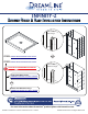
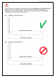
INFINITY-Z SHOWER DOOR & BASE INSTALLATION INSTRUCTIONS Wall Profile with Flange STEP 1: Shower Base Installation Instructions OR STEP 2: Shower Door Installation Instructions ! CHOOSE the APPROPRIATE MANUAL for your model version Wall Profile without Flange Wall Profile WITH Flange: INFINITY-Z Manual Ver 4 Rev 5 062017 OR Wall Profile WITHOUT Flange: INFINITY-Z Manual Ver 5 Rev 2 012020 1-866-731-2244 For more information about DreamLine® products please visit DreamLine.
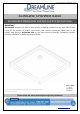
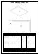
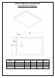
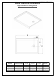
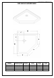
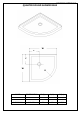
©2018 DreamLine. All Rights Reserved SLIMLINE SHOWER BASE SHOWER BASE DIMENSIONS AND INSTALLATION INSTRUCTIONS IMPORTANT DreamLine® reserves the right to alter, modify or redesign products at any time without prior notice for the purpose of product improvement and customer experience. Please refer to the model’s web page on DreamLine.com for the latest technical drawings, installation manuals, warranty information or additional product details.
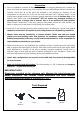
©2018 DreamLine. All Rights Reserved Preparation 1. Prior to installation, examine all boxes and packages for shipping damage and compare the piece count with your packing slip. After opening all boxes and packages read this introduction carefully. Check that all of the parts are included in the package by checking off the components on the parts list.
©2018 DreamLine.
©2018 DreamLine.
©2018 DreamLine.
©2018 DreamLine.
©2018 DreamLine.
©2018 DreamLine.
©2018 DreamLine.
©2018 DreamLine.
©2018 DreamLine.
©2018 DreamLine.
©2018 DreamLine. All Rights Reserved Shower Base Cross Section Diagram Finished Wall Shower Base Cement board (2"×4") Stud Mortar Drain* * not included This product should be installed by someone familiar with the construction requirements for this type of project and the care necessary for the safe installation and operation of the product.
©2018 DreamLine. All Rights Reserved Shower Base Installation - Preparation 1. Ensure that the floor and the studs are at right angles. Provide a 5”×5” opening in the subfloor for the drain. The 2” PVC waste pipe should extend above the surface of the sub-floor according to the drain installation instructions and the height of the Shower base. Refer to the product drawings and tables in this installation manual for the drain location.
©2018 DreamLine. All Rights Reserved 2. Install the shower drain (NOT INCLUDED) according to the drain installation manual (supplied with the drain). (Fig 2) Fig 2 3. Place the tray into the designated position so that the Drain cutout drops around the Drain Pipe and butt the Shower Base up against the studs. (Fig 3) Lower the base over the drain pipe and set it into place against the studs.
©2018 DreamLine. All Rights Reserved 4. Level the tray and place marks on the studs above the upper edge of the tile flange. (Fig 4) Level base in two directions Fig 4 5. Mix the bedding material (Mortar, cement-sand mix, etc.) Concrete or plaster is not recommended. Apply enough bedding material to support the entire bottom of the shower base. This will add additional stability and prevent the base from shifting position.
©2018 DreamLine. All Rights Reserved 6. After the bedding material has been poured and before it sets, place the shower base into the position with the drain assembly sliding over the PVC waste pipe. It will be necessary to push the shower base until the top of the tile flange aligns with the marks drawn on the studs and the front edge is contacting the rough floor along the entire length of the shower base. Ensure that the base is level in all directions.
©2018 DreamLine.
©2018 DreamLine. All Rights Reserved Product Maintenance BASES and BACKWALLS: To ensure long lasting life for your acrylic base and/or back walls: wipe them off after each use with a soft cloth. To clean the acrylic base or back walls use non-abrasive sprays or cream-based cleaners. Avoid the use of aerosol spray cleaners. Never use abrasive cleansers, metal brushes or scrapers that could scratch or dull the surface.
TEL: 866-731-2244 FAX: 866-857-3638 DREAMLINE.COM For more information on DreamLine® Shower Doors and Enclosures please visit DreamLine.com ©2018 DreamLine.
INFINITY-Z SHOWER DOOR / TUB DOOR INSTALLATION INSTRUCTION IMPORTANT DreamLine® reserves the right to alter, modify or redesign products at any time without prior notice. For the latest up-to-date technical drawings, manuals, warranty information or additional details please refer to your model’s web page on DreamLine.
Table of Contents Section title Preparation Tools Parts List Installation Steps Wheel Assemblies Vinyl Seals Product maintenance INFINITY-Z manual Ver 4 Rev 5 06/2017 Page # 2 3 5 6-13 11 12 14 ©2017 DreamLine.
Preparation 1. Prior to installation, examine all boxes and packages for shipping damage and compare the piece count with the packing slip. After opening all boxes and packages read this introduction carefully. Check that all of the necessary parts are included in the package by checking off the components on the “Detailed Diagram of Shower Door Components”.
Tools Level Silicone/Caulk Tape Measure Phillips Screwdriver Pencil Power Drill Drill bit (Ø=5/16") (D=8mm) Drill bit (Ø=1/8") (D=3mm) Miter saw or Hacksaw Hammer Top Tip: Measure the finished opening before Tip: Prior to installation, cover the shower/tub drain with tape to prevent losing screws or small parts. Tip: Set screw gun clutch to low setting when installing screws and bolts to prevent stripping the heads. Middle Bottom W ©2017 DreamLine.
Detailed Diagram of shower door components 13 8 14 12 11 10 2 1 9 5 15 16 3 7 18 4 6 ©2017 DreamLine.
Parts List DESCRIPTION QTY PART# DESCRIPTION QTY 01 Glass profile 2pcs 10 Round head screw ST4.2x25 8pcs 02 Wall profile 2pcs 11 Round head screw ST4.2x10 4pcs 03 Guide rail (top and bottom) 2pcs 12 Flat head screw ST4.
Installation steps 1. Measure the distance between the two finished walls at the top (at model height: 58” or 72”), middle and bottom. The wall profiles will adjust for out-of-plumb conditions, so use the smallest measurement as the “finished opening” dimension to determine the finished cut length in Step #2. (Fig 1) NOTE: The Top and Bottom Guide Rails (#03) are shorter than the model size by design.
3. After the Top and Bottom Guide Rails (#03) have been cut, you will need to re-install the roller stopper on each Top and Bottom Guide Rails (#03) on the end that has been cut off (the door end). Remove the existing stopper. Mark the drilling hole at the distance of 3-1/8” from the cut end of the Top and Bottom Guide Rails (#03). Drill a new hole using a Ø1/8” drill bit; then re-secure the stopper with the screw.
5. Slide the Stationary Glass (#05) fully into the groove of the Glass Profile (#01), and then secure the Glass Holder (#16) to the Bottom Guide Rail (#03) with the Flat Head Screw ST4.2x16 (#12). (Fig 6) ! NOTE: Use caution when installing the stationary glass into the frame to prevent damage to the edges of the glass. Bottom rail cut away to show detail Inside add a bead of silicone to the bottom rail (optional) prior to installing the stationary glass Fig 6 6.
8. Slide the Wall Profiles (#02) all the way onto the Glass Profiles (#01) on both sides. Make sure the flange of the wall profile faces inside the shower. (Fig 8) Inside Fig 8 9. Move the assembled frame into the designated position on the shower base*, bathtub or threshold (depending on your installation), and push the Wall Profiles (#02) tight to the walls to compensate for any out-of-plumb conditions. Push the bottom rail down tight to the threshold and adjust the frame to a vertical position.
10. Use a helper to hold the assembly in position and mark the drill holes on the wall through the holes on the flange of the Wall Profiles (#02). Gently set the assembled unit aside; drill the holes using a Ø5/16” drill bit and insert the Wall Anchors (#14). Apply silicone along the Wall Profile (#02) and around the holes on the wall. Also apply silicone caulk under the Bottom Guide Rail (#03).
12. Fasten the top and the bottom Wheel Assemblies (#17) to the Door Glass (#04). The top wheels can adjust the door level using the adjustable bolt and lock nut. The bottom wheel has a press button to fix the wheel onto the Bottom Guide Rail (#03). The wheels must face towards the outside of the shower. Be sure that the handle holes are on the correct side for the installation. (Fig 12) NOTE: The lock nut of the upper wheel (Fig 12.4) and the press button of the bottom wheel (Fig 12.
14. Install the Handle (#06) to the Door Glass (#04). Press the Anti-Water Strips (#07) onto the vertical edges of the Stationary Glass (#05) and both vertical edges of the Door Glass (#04). Insert the Seal Gasket (#15) into the Glass Profile (#01) starting from the bottom (Fig. 14.3). (Fig 14) 1 2 3 Outside Fig 14 TIP: The longer Anti-Water Strips (#07) attach to the edges of the Door Glass (#04) and the shorter strip attaches to the edge of the Stationary Glass (#05). 15.
16. Apply good quality mildew-resistant silicone along the profiles and guide rails; on the seams between the bottom guide rail and the profiles as well as along the shower base or threshold. Allow 24 hours for the silicone to cure before using the shower. (Fig 16) ©2017 DreamLine.
Product Maintenance BASES and BACKWALLS: To ensure long-lasting life for your acrylic back walls, wipe them off after each use with a soft cloth. To clean the acrylic back walls use non-abrasive sprays or cream based cleaners. Avoid the use of aerosol spray cleaners. Never use abrasive cleansers, metal brushes or scrapers that could scratch or dull the surface. GLASS: To ensure long-lasting life for your glass shower products, wipe them off after each use with a soft cloth.
TEL: 866-731-2244 FAX: 866-857-3638 DREAMLINE.COM For more information on DreamLine® Shower Doors and Enclosures please visit DreamLine.com ©2017 DreamLine.
INFINITY-Z ® SHOWER AND TUB DOOR INSTALLATION d INSTRUCTIONS e e n v i r LMANUALsPRIOR PLEASE REVIEW THIS ENTIRE TO INSTALLATION e m e a R e Dr ghts © Ri l l A MODEL #s SHDR-0960580-## d e e n v i r L e s m e a R e r s D ght © Ri All MODEL #s SHDR-0948720-## SHDR-0954720-## SHDR-0960720-## Left-hand door installation shown ® ## = finish 01-Chrome 04-Brushed Nickel 06-Oil Rubbed Bronze FR-Frosted Glass IMPORTANT! DreamLine® reserves the right to alter, modify or redesign products at any time without
d e e n v i r L e s m e a R e r s D ght © Ri All ® Record the following purchase information for your records or in the event you need to contact DreamLine®: Purchase Order Number Store/Vendor Purchased From Installation Date OD Number (optional) Installed By: SKU Number INFINITY-Z Shower and Tub Door Manual Ver 5 Rev 2 012020 located on the shipping box or label if available.
Section Title General Preparations and Warnings Model Specific Preparation Adjustable Wall Profile System Tools Detailed Diagram of Shower Door Components Parts List Installation Steps Top and Bottom Roller Assembly Installation Handle and Vinyl(s) Installation Decorative Cover with Washer Installation Product Maintenance Troubleshooting Factory Parts Information d e e n v i r L e s m e a R e r s D ght © Ri l l A ® d e e n Symbol Legendi v r L e s m e a R e r s D ght © Ri All Page # 2 3 4 5 6 7-8 9-24 20
d e e ® n i e erv ed L s m n v e i r a L R e e Dr regahmts Res © DRi hts ©All Rig l l A IMPORTANT • GENERAL PREPARATION • • DreamLine® reserves the right to alter, modify or redesign products any time without prior notice for product improvement and customer experience. Please refer to the model’s web page on DreamLine.com for the latest technical drawings, installation manuals, warranty information or additional product details.
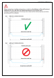
©2020 DreamLine® All Rights Reserved Model Specific Preparation 1” Out-of-Plumb Adjustment; Verify threshold and walls with a level Threshold must be level 1” minimum threshold d e e n v i r L e s m e a R e r s D ght © Ri l l A ® ±0.0 1” (25.4mm) minimum flat threshold ±0.0 ! Threshold must be level ! DO NOT attach the handle and/or towel bar to the glass until instructed to do so. DO NOT attempt to use the handle/towel bar to lift the glass during installation.
©2020 DreamLine® All Rights Reserved Adjustable Wall Profile System ! Wall Profile The Glass Profiles can be adjusted within the Wall Profiles for overall width or to correct for out-of-plumb conditions within the model size. Screw them together after making final adjustments. ® Glass Profile d ® e e n iine errvved L s L m e e a s m R e e DDrreaghttss R © © ll RRiigh AAll Wall Profile Glass Profile 1” m ax d e e n iine errvved L s L m e e a s m R e e DDrreaghttss R © © ll RRiigh AAll ® ® ST4.
©2020 DreamLine® All Rights Reserved Tools Tape Measure Level Phillips Screwdriver Pencil d e e n v i r L e s m e a R e r s D ght © Ri l l A Silicone ® Drill Bit Ø5/16" (8mm) Drill Bit Drill Bit Ø3/16" Ø1/8" (4.
©2020 DreamLine® All Rights Reserved Detailed Diagram of Shower Door Components 03 d e e n v i r L e s m 17a e a R e r s D ght © Ri l l A ® inside 07 02 13 09 11 14 18 inside 08 05 04 12 06 03 17b inside 16 d e e n v i r L e s m e a R e r s D ght © Ri All inside ® 10 inside 01 Left-hand door installation shown INFINITY-Z Shower and Tub Door Manual Ver 5 Rev 2 012020 6
©2020 DreamLine® All Rights Reserved Parts List 01 02 03 d e e n v i r L e x2 s x2 m e a R e r s D ght © Ri05 06 l l A ® Glass Profile 04 Door Glass Wall Profile x1 10 ST4.0x25mm Pan Head screw Inline Panel Glass x1 08 07 Anti-water Strips 1 Short, 2 Long Guide Rail (Top and Bottom) Handle x8 ® Push-in Glazing Vinyl ST4.0x10mm Pan head screw INFINITY-Z Shower and Tub Door Manual Ver 5 Rev 2 012020 x1 09 d e e x1 n v i r L e s m e a R e r s D 11ght 12 © Ri All x3 x2 ST4.
13 ©2020 DreamLine® All Rights Reserved Parts List 15 14 d e e n v i r L e x4 s x8 m e a R e r s D ght © Ri17a 17b 17a l l A ® Decorative Cover (with washer) 16 Glass Clip Wall Anchor x2 Wheel Assembly (Top) x2 Vinyl Insert Wheel Assembly (Bottom) x1 x2 18 Towel Bar d e e n v i r L e s m e a R e r s D ght © Ri All x1 INFINITY-Z Shower and Tub Door Manual Ver 5 Rev 2 012020 ® 8
©2020 DreamLine® All Rights Reserved Installation Steps 1 Top *at model height d e e n v i r L e s m e a R e r s D ght © Ri l l A ® ________” Middle ________” Bottom ________” Fig 1 TIP NOTE W d e e n v i r L e s m e a R e r s D ght © Ri All ®determine Use the smallest measurement from Fig 1 to the finished cut length of the Guide Rails (#03). The Top and Bottom Guide Rails (#03) are shorter than the model size by design.
- = Finished Opening (W) MODEL SIZE *from Table A Cut-off Length (C) *from Door End only Panel Side d e e n v i r L e s m e a R e s Dr ghtCenter © Ri All ® Cut the Top and Bottom Guide Rails (#03) from the Door End only, (which is the end farthest from the Glass Clip hole) and cut each rail to the same length (D) from the same end.
©2020 DreamLine® All Rights Reserved 3 1 2 3-1/8” to the center of the hole r doo end d e e n v i r L e s m e a R e Dr ghts © Ri Ø1/8” l l A ® r doo end 3 door end d e e n v i r L e s m e a R e Dr ghts © Ri All ® Fig 3 /8” 3-1 nter e ce to th e hole of th Top Rail Door End Parts Needed Bottom Rail /8” 3-1he center Tools Needed 03 to t e hole of th x2 INFINITY-Z Shower and Tub Door Manual Ver 5 Rev 2 012020 11
©2020 DreamLine® All Rights Reserved 4 top d e e n v i r L e s m e a R e Dr ghts © Ri All ® ® Fig 4 d ve e r n i L e s m e a R e Dr ghts © Ri All bottom TIP For ease of installation: Add liquid soap, wax, or lubricant to the screws prior to attaching the Glass Profiles (#01) to the Guide Rails (#03). Use a low setting on the screw gun to prevent stripping the screws.
©2020 DreamLine® All Rights Reserved 5 d e e n v i r L e s m e a R e Dr ghts © Ri All ® Fig 5 d e e n v i r L e s m 2 e a R e Dr ghts © Ri All ® 1 Holes in both profiles must line up inside inside Parts Needed 02 NOTE The holes in the Wall Profiles (#02) are off-center, and must line up with the corresponding holes in the Glass Profiles (#01).
NOTE ©2020 DreamLine® All Rights Reserved 6 At this step, decide on the handing of the door and panel prior to placing the assembly into the opening to mark the location of the holes for drilling. Flip the assembly so that the Inline Panel Glass (#06) will be installed on the desired side of the opening. d e e n v i r L e s m e a R e Dr ghts © Ri All ® 1 ±0.
©2020 DreamLine® All Rights Reserved 7 1 d e e n v i r L e s m e a R e Dr ghts © Ri All ® 2 Ø3/16” Drill Bit 3* *see NOTE d e e n v iFig 7 er L s m e a R e r s D ght © Ri All ® NOTE If a stud is present behind the wall, drill a hole using a Ø3/16” drill bit up to the stud, drill an Ø1/8“ pilot hole into the stud and do not use wall anchors. If no stud is present, drill the hole using a Ø5/16” drill bit and insert Wall Anchors (#14) as shown in Fig 7.3.
! ©2020 DreamLine® All Rights Reserved 8 Before securing the frame assembly, bring the Door Glass (#04) into the shower area and lean it safely against the wall, using padding to protect the glass, walls, and base. Make sure the handle holes on the Door Glass (#04) are on the correct side for installation. The Wheel Assemblies (#17a/17b) can be attached prior to setting the glass into the shower.
©2020 DreamLine® All Rights Reserved 9 1 wall profiles 2 3 d e e n v i r L e s m e a R e Dr ghts bottom © Ri rail All ® ne silicone 4 silico 5 ST4.0×55 6 ST4.0×55 wall wall Overhead View Fig 9 TIP d e e n v i r L e s m e a R e Dr ghts © Ri All Extender Driver Bit recommended for the installation of these screws. ® Parts Needed NOTE The screwheads on the ST4.
©2020 DreamLine® All Rights Reserved 10 1 2 d e e n v i rinside L e s m e a R e Dr ghts © i inside R All ® Fig 10a NOTE For models with Frosted glass, install the textured (Frosted) surface facing towards the outside of the shower. Use caution when installing the Inline Panel Glass (#05) into the frame to prevent damage to the edges of the glass.
©2020 DreamLine® All Rights Reserved 11 d e e n v i r L e s m e a R e r s D ght © Ri l l A ® inside d e e in erv L s m e a Fig 11 R e r s D ght © Ri All ® Right-hand panel installation shown Parts Needed ! To prevent scratching or damaging the glass and aluminum, DO NOT use a screwdriver or other metal tool to install the Push-in Glazing Vinyl (#08). Use a plastic putty knife or similar if necessary.
©2020 DreamLine® All Rights Reserved 12 d e e n v i r L e s m e a R doo e r r gla s t sD s h © Rig inside l l A ® inside d e e n v i r L e s m e a R e r s D ght © Ri All ® Fig 12 *Left-hand door installation shown NOTE Top Wheels The lock nut on the Top Roller Assembly (#17a) and the push-button on the Bottom Roller Assembly (#17b) should both be installed pointing up. DO NOT overtighten the Roller Assemblies (#17a/17b).
©2020 DreamLine® All Rights Reserved 13 1 2 inside d e e n v i r L e s m e a R e r s D ght © Ri l l bottom A ® align and install 3 inside lift up 4 adjust* align and install d e e n v i r L e s m e a R e r s D ght © Ri All top ® Fig 13 NOTE *If necessary: Adjust the Top Roller Assemblies (#17a) for smoother operation.
©2020 DreamLine® All Rights Reserved Handle and Vinyl Installation 14 d e e n v i r L e s m e a R e Dr ghts © Ri All ® inside door door glass Inline Panel Glass panel door glass outside Fig 14 d e e n v i r L e s m e a R e Dr ghts © Ri All NOTE ® The longer Vertical Vinyl Seals (#07) attach to the edges of the Door Glass (#04); the shorter Vertical Vinyl Seal (#07) attaches to the edge of the Inline Panel Glass (#05).
DO NOT drill the profiles throughout, ONLY through the first layer of the Wall Profile (#02) and Glass Profile (#01). ! 1 3/4” ll wa ©2020 DreamLine® All Rights Reserved 15 2 d e e n v i r L e s wall m e a R e r s D ght © Ri l l A ® Ø1/8” inside inside 3 4 ll wa ll wa inside inside d e e n iFig 15 erv L s m e a R e r s D ght © Ri All ® NOTE Make sure that the bottom rail is tight to the threshold before screwing the wall profiles and glass profiles together NOTE The ST4.
©2020 DreamLine® All Rights Reserved 16 NOTE The surfaces need to be clean and free of debris before applying silicone. d e e n v i r L e s24 m e a R e r s D ght Hours © Ri l l A ® d e e n v i r L e s m e a R e r s D ght © Ri All ® Fig 16 ! Tools Needed Allow 24 hours for the silicone caulk to cure before using shower.
©2020 DreamLine® All Rights Reserved Product Maintenance BASES and BACKWALLS: To ensure long lasting life for your acrylic back walls: wipe them off after each use with a soft cloth. To clean the acrylic back walls use non-abrasive sprays or cream based cleaners. Avoid the use of aerosol spray cleaners. Never use abrasive cleansers, metal brushes or scrapers that could permanently scratch or dull the surface.
Problem/Symptom Missing Parts Suggested Solution •Check all shipping/packaging material for missing parts/components. •If not found, contact DreamLine Customer Support [1-855-8312126] to order factory part replacement. d e e n v i r L e s m e a R e r s D ght © Ri l l A ® Page(s) ―― Leakage: underneath Bottom Guide Rail (#03) •Make certain that the bottom rail is tight to the threshold and that silicone is creating a seal along the entire length of the bottom rail.
INFINITY-Z Shower and Tub Door Manual Ver 5 Rev 2 012020 Product Parts Information INFINITY-Z 48x72 Clear Glass ITEM # FACTORY PARTS INFORMATION FACTORY PART NUMBER ITEM DESCRIPTION QTY 01 04002011-1830 / 04002041-1830 / 04002061-1830 Left or Right Glass Profile for 6mm (1/4in) Glass 2 pcs 02 04183011-1830 / 04183041-1830 / 04183061-1830 Left or Right Wall Profile 2 pcs 03 04001011-1134 / 04004011-1134 / 04006011-1134 Top or Bottom Guide Rail 2 pcs 04 010021014 Door Glass 1 pc 05 0100
INFINITY-Z Shower and Tub Door Manual Ver 5 Rev 2 012020 Product Parts Information INFINITY-Z 48x72 Frosted Glass ITEM # FACTORY PARTS INFORMATION ITEM DESCRIPTION FACTORY PART NUMBER QTY 01 04002011-1830 / 04002041-1830 / 04002061-1830 Left or Right Glass Profile for 6mm (1/4in) Glass 2 pcs 02 04183011-1830 / 04183041-1830 / 04183061-1830 Left or Right Wall Profile 2 pcs 03 04001011-1134 / 04004011-1134 / 04006011-1134 Top or Bottom Guide Rail 2 pcs 04 010021016 Door Glass 1 pc 05 010
INFINITY-Z Shower and Tub Door Manual Ver 5 Rev 2 012020 Product Parts Information INFINITY-Z 54x72 Clear Glass ITEM # FACTORY PARTS INFORMATION ITEM DESCRIPTION FACTORY PART NUMBER QTY 01 04002011-1830 / 04002041-1830 / 04002061-1830 Left or Right Glass Profile for 6mm (1/4in) Glass 2 pcs 02 04183011-1830 / 04183041-1830 / 04183061-1830 Left or Right Wall Profile 2 pcs 03 04001011-1283 / 04004011-1283 / 04006011-1283 Top or Bottom Guide Rail 2 pcs 04 010022011 Door Glass 1 pc 05 01002
INFINITY-Z Shower and Tub Door Manual Ver 5 Rev 2 012020 Product Parts Information INFINITY-Z 54x72 Frosted Glass ITEM # FACTORY PARTS INFORMATION ITEM DESCRIPTION FACTORY PART NUMBER QTY 01 04002011-1830 / 04002041-1830 / 04002061-1830 Left or Right Glass Profile for 6mm (1/4in) Glass 2 pcs 02 04183011-1830 / 04183041-1830 / 04183061-1830 Left or Right Wall Profile 2 pcs 03 04001011-1283 / 04004011-1283 / 04006011-1283 Top or Bottom Guide Rail 2 pcs 04 010022013 Door Glass 1 pc 05 010
INFINITY-Z Shower and Tub Door Manual Ver 5 Rev 2 012020 Product Parts Information INFINITY-Z 60x72 Clear Glass ITEM # FACTORY PARTS INFORMATION ITEM DESCRIPTION FACTORY PART NUMBER QTY 01 04002011-1830 / 04002041-1830 / 04002061-1830 Left or Right Glass Profile for 6mm (1/4in) Glass 2 pcs 02 04183011-1830 / 04183041-1830 / 04183061-1830 Left or Right Wall Profile 2 pcs 03 04001011-1437 / 04004011-1437 / 04006011-1437 Top or Bottom Guide Rail 2 pcs 04 010021010 Door Glass 1 pc 05 01002
INFINITY-Z Shower and Tub Door Manual Ver 5 Rev 2 012020 Product Parts Information INFINITY-Z 60x72 Frosted Glass ITEM # FACTORY PARTS INFORMATION ITEM DESCRIPTION FACTORY PART NUMBER QTY 01 04002011-1830 / 04002041-1830 / 04002061-1830 Left or Right Glass Profile for 6mm (1/4in) Glass 2 pcs 02 04183011-1830 / 04183041-1830 / 04183061-1830 Left or Right Wall Profile 2 pcs 03 04001011-1437 / 04004011-1437 / 04006011-1437 Top or Bottom Guide Rail 2 pcs 04 010021011 Door Glass 1 pc 05 010
INFINITY-Z Shower and Tub Door Manual Ver 5 Rev 2 012020 Product Parts Information INFINITY-Z 60x58 Clear Glass ITEM # FACTORY PARTS INFORMATION FACTORY PART NUMBER ITEM DESCRIPTION QTY 01 04002011-1474 / 04002041-1474 / 04002061-1474 Left or Right Glass Profile for 6mm (1/4in) Glass 2 pcs 02 04183011-1474 / 04183041-1474 Left or Right Wall Profile 2 pcs 03 04001011-1437 / 04004011-1437 / 04006011-1437 Top or Bottom Guide Rail 2 pcs 04 010021007 Door Glass 1 pc 05 010022001 Inline Pa
d e e n v i r L e s m e a R e r s D ght © Ri All ® d e e n v i r L e s m e a R e r s D ght © Ri All ® TEL: 866-731-2244 FAX: 866-857-3638 DREAMLINE.COM For more information on DreamLine® Shower Doors and Enclosures please visit DreamLine.