Infinity-Z Shower Door & Base SHOWER DOOR & BASE INSTALLATION INSTRUCTIONS IMPORTANT DreamLine® reserves the right to alter, modify or redesign products at any time without prior notice. For the latest up-to-date technical drawings, manuals, warranty information or additional details please refer to your model’s web page on DreamLine.
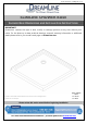
©2018 DreamLine. All Rights Reserved SLIMLINE SHOWER BASE SHOWER BASE DIMENSIONS AND INSTALLATION INSTRUCTIONS IMPORTANT! DreamLine® reserves the right to alter, modify or redesign products at any time without prior notice. For the latest up-to-date technical drawings, manuals, warranty information or additional details please refer to your model’s web page on DreamLine.
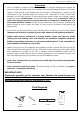
©2018 DreamLine. All Rights Reserved Preparation 1. Prior to installation, examine all boxes and packages for shipping damage and compare the piece count with your packing slip. After opening all boxes and packages read this introduction carefully. Check that all of the needed parts are included in the package by checking off the components on the “Detailed Diagram of Shower Door Components”.
©2018 DreamLine.
©2018 DreamLine.
©2018 DreamLine.
©2018 DreamLine.
©2018 DreamLine.
©2018 DreamLine.
©2018 DreamLine.
©2018 DreamLine.
©2018 DreamLine.
©2018 DreamLine.
©2018 DreamLine.
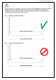
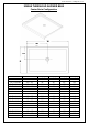
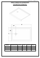
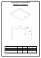
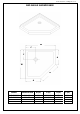
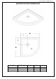
©2018 DreamLine. All Rights Reserved Shower Base Installation - Preparation 1. Ensure that the floor and the studs are at right angles. Provide a 5”×5” opening in the subfloor for the drain. The 2” PVC waste pipe should extend above the surface of the sub-floor according to the drain installation instructions and the height of the Shower base. Refer to the product drawings and tables in this installation manual for the drain location. 90° 90° 90° See Fig. 1 and Fig. 2 for details.
©2018 DreamLine. All Rights Reserved 2. Install the shower drain (NOT INCLUDED) according to the drain installation manual (supplied with the drain). See Fig. 3 for example Fig. 3 3. Place the tray into the designated position so that the Drain cutout drops around the Drain Pipe and butt the Shower Base up against the studs. See Fig. 4 for details. Lower the base over the drain pipe and set it into place against the studs. Fig.
©2018 DreamLine. All Rights Reserved 4. Level the tray and place marks on the studs above the upper edge of the tile flange. See Fig. 5 for details. Level base in two directions Fig. 5 5. Mix the bedding material (Mortar, cement-sand mix, etc.) Concrete or plaster is not recommended. Apply enough bedding material to support the entire bottom of the shower base. This will add additional stability and prevent the base from shifting position. See Fig. 6 for details. Mortar Fig.
©2018 DreamLine. All Rights Reserved 6. After the bedding material has been poured and before it sets, place the shower base into the position with the drain assembly sliding over the PVC waste pipe. It will be necessary to push the shower base until the top of the tile flange aligns with the marks drawn on the studs and the front edge is contacting the rough floor along the entire length of the shower base. Ensure that the base is level in all directions.
©2018 DreamLine. All Rights Reserved Fig.
©2018 DreamLine. All Rights Reserved Product Maintenance BASES and BACKWALLS: To ensure long lasting life for your acrylic base and/or back walls: wipe them off after each use with a soft cloth. To clean the acrylic base or back walls use non-abrasive sprays or cream based cleaners. Avoid the use of aerosol spray cleaners. Never use abrasive cleansers, metal brushes or scrapers that could scratch or dull the surface.
TEL: 866-731-2244 FAX: 866-857-3638 DREAMLINE.COM For more information on DreamLine® Shower Doors and Enclosures please visit DreamLine.
INFINITY-Z SHOWER DOOR / TUB DOOR INSTALLATION INSTRUCTION IMPORTANT DreamLine® reserves the right to alter, modify or redesign products at any time without prior notice. For the latest up-to-date technical drawings, manuals, warranty information or additional details please refer to your model’s web page on DreamLine.
Table of Contents Section title Preparation Tools Parts List Installation Steps Wheel Assemblies Vinyl Seals Product maintenance INFINITY-Z manual Ver 4 Rev 5 06/2017 Page # 2 3 5 6-13 11 12 14 ©2017 DreamLine.
Preparation 1. Prior to installation, examine all boxes and packages for shipping damage and compare the piece count with the packing slip. After opening all boxes and packages read this introduction carefully. Check that all of the necessary parts are included in the package by checking off the components on the “Detailed Diagram of Shower Door Components”.
Tools Level Silicone/Caulk Tape Measure Phillips Screwdriver Pencil Power Drill Drill bit (Ø=5/16") (D=8mm) Drill bit (Ø=1/8") (D=3mm) Miter saw or Hacksaw Hammer Top Tip: Measure the finished opening before Tip: Prior to installation, cover the shower/tub drain with tape to prevent losing screws or small parts. Tip: Set screw gun clutch to low setting when installing screws and bolts to prevent stripping the heads. Middle Bottom W ©2017 DreamLine.
Detailed Diagram of shower door components 13 8 14 12 11 10 2 1 9 5 15 16 3 7 18 4 6 ©2017 DreamLine.
Parts List DESCRIPTION QTY PART# DESCRIPTION QTY 01 Glass profile 2pcs 10 Round head screw ST4.2x25 8pcs 02 Wall profile 2pcs 11 Round head screw ST4.2x10 4pcs 03 Guide rail (top and bottom) 2pcs 12 Flat head screw ST4.
Installation steps 1. Measure the distance between the two finished walls at the top (at model height: 58” or 72”), middle and bottom. The wall profiles will adjust for out-of-plumb conditions, so use the smallest measurement as the “finished opening” dimension to determine the finished cut length in Step #2. (Fig 1) NOTE: The Top and Bottom Guide Rails (#03) are shorter than the model size by design.
3. After the Top and Bottom Guide Rails (#03) have been cut, you will need to re-install the roller stopper on each Top and Bottom Guide Rails (#03) on the end that has been cut off (the door end). Remove the existing stopper. Mark the drilling hole at the distance of 3-1/8” from the cut end of the Top and Bottom Guide Rails (#03). Drill a new hole using a Ø1/8” drill bit; then re-secure the stopper with the screw.
5. Slide the Stationary Glass (#05) fully into the groove of the Glass Profile (#01), and then secure the Glass Holder (#16) to the Bottom Guide Rail (#03) with the Flat Head Screw ST4.2x16 (#12). (Fig 6) ! NOTE: Use caution when installing the stationary glass into the frame to prevent damage to the edges of the glass. Bottom rail cut away to show detail Inside add a bead of silicone to the bottom rail (optional) prior to installing the stationary glass Fig 6 6.
8. Slide the Wall Profiles (#02) all the way onto the Glass Profiles (#01) on both sides. Make sure the flange of the wall profile faces inside the shower. (Fig 8) Inside Fig 8 9. Move the assembled frame into the designated position on the shower base*, bathtub or threshold (depending on your installation), and push the Wall Profiles (#02) tight to the walls to compensate for any out-of-plumb conditions. Push the bottom rail down tight to the threshold and adjust the frame to a vertical position.
10. Use a helper to hold the assembly in position and mark the drill holes on the wall through the holes on the flange of the Wall Profiles (#02). Gently set the assembled unit aside; drill the holes using a Ø5/16” drill bit and insert the Wall Anchors (#14). Apply silicone along the Wall Profile (#02) and around the holes on the wall. Also apply silicone caulk under the Bottom Guide Rail (#03).
12. Fasten the top and the bottom Wheel Assemblies (#17) to the Door Glass (#04). The top wheels can adjust the door level using the adjustable bolt and lock nut. The bottom wheel has a press button to fix the wheel onto the Bottom Guide Rail (#03). The wheels must face towards the outside of the shower. Be sure that the handle holes are on the correct side for the installation. (Fig 12) NOTE: The lock nut of the upper wheel (Fig 12.4) and the press button of the bottom wheel (Fig 12.
14. Install the Handle (#06) to the Door Glass (#04). Press the Anti-Water Strips (#07) onto the vertical edges of the Stationary Glass (#05) and both vertical edges of the Door Glass (#04). Insert the Seal Gasket (#15) into the Glass Profile (#01) starting from the bottom (Fig. 14.3). (Fig 14) 1 2 3 Outside Fig 14 TIP: The longer Anti-Water Strips (#07) attach to the edges of the Door Glass (#04) and the shorter strip attaches to the edge of the Stationary Glass (#05). 15.
16. Apply good quality mildew-resistant silicone along the profiles and guide rails; on the seams between the bottom guide rail and the profiles as well as along the shower base or threshold. Allow 24 hours for the silicone to cure before using the shower. (Fig 16) ©2017 DreamLine.
Product Maintenance BASES and BACKWALLS: To ensure long-lasting life for your acrylic back walls, wipe them off after each use with a soft cloth. To clean the acrylic back walls use non-abrasive sprays or cream based cleaners. Avoid the use of aerosol spray cleaners. Never use abrasive cleansers, metal brushes or scrapers that could scratch or dull the surface. GLASS: To ensure long-lasting life for your glass shower products, wipe them off after each use with a soft cloth.
TEL: 866-731-2244 FAX: 866-857-3638 DREAMLINE.COM For more information on DreamLine® Shower Doors and Enclosures please visit DreamLine.com ©2017 DreamLine.