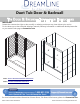
Duet Tub Door & Backwall TUB DOOR & BACKWALL INSTALLATION INSTRUCTIONS IMPORTANT DreamLine® reserves the right to alter, modify or redesign products at any time without prior notice. For the latest up-to-date technical drawings, manuals, warranty information or additional details please refer to your model’s web page on DreamLine.
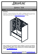
QWALL TUB TUB ACRYLIC BACK WALL INSTALLATION INSTRUCTIONS IMPORTANT DreamLineTM reserves the right to alter, modify or redesign products at any time without prior notice. For the latest up-to-date technical drawings, manuals or any other details please refer to the support.BathAuthority.com web page. Please carefully read the instructions before installing.
Preparation 1. After opening all boxes and packages, read this introduction carefully. Check that all of the needed parts are included in the package, by marking all the components on the “Detailed Diagram of Tub Back Wall Components”. Examine boxes and packages for shipping damage. If the unit has been damaged, has a finishing defect, or has missing parts, please contact our customer support department within 3 business days of the delivery date.
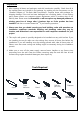
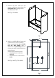
Detailed Diagram of Tub Back Wall Components 4 2 1 5 3 6 7 8 9 10 Packing List 01 Side panel 2pcs 06 Wall anchor 21pcs 02 Back panel 2pcs 07 Countersunk screw ST4.2×30 21pcs 03 Decorative edge molding 2pcs 08 Decorative cover 15pcs 04 Corner cover 2pcs 09 Glass shelf 2pcs 05 Wall cover 1pc 10 Shelf bracket 6pcs NOTE: Unpack your unit carefully and inspect it. Lay it out and identify all parts using the detailed diagram and packing list in your manual as a reference.
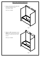
Back Panel Installation Instruction 1. Measure the distance of the back wall of the tub (corner to corner) The distance is “W” W See Fig. 1 for details. Fig. 1 W/2 2. Divide the W measurement by 2 (W/2). Place a mark on the back wall and draw a vertical line from top to bottom. W/2 See Fig. 2 for details. Fig. 2 Rev 1.
3. Measure the side walls from the corner to the front point where the Side panel (01) is going to end. This distance is “D”. D See Fig. 3 for details. D Fig. 3 D - 1” 1” Trim line 4. Verify on which side of your tub wall the fixtures will be installed. Place a mark on the side wall (NB: not the side panel!) with a distance of 1” (one inch) from the corner and draw a vertical line from top to bottom.
Fig. 5 5. Attach the Center cover (05) vertically at the center point along the line and mark the drilling holes through the predrilled holes on the Center cover. Drill the holes using Ø5/16” drill bit and insert the Wall Anchors (06). 1 See Fig. 6 and Fig. 7 for details. 2 3 Ø5/16” 4 Fig. 6 Rev 1.
Fig. 7 6. Attach the Corner cover (04) to the corner of the wall and mark the drilling holes through the predrilled holes on the Corner cover. Drill the holes using Ø5/16” drill bit and insert the Wall Anchors (06). See Fig. 8 and Fig. 9 for details 1 3 Ø5/16” 2 4 Fig. 8 Rev 1.
Fig. 9 7. Determine the position of both Back panels (02). NOTE: a) Narrow side of the Back panel cannot be trimmed and should face the center of the Back wall. b) Wide side of the Back panel can be trimmed to the size of the wall and should face the corner. W/2-1” W/2-1” b a Place a mark on the wide side of the Back panel with a distance of (W/2 – 1”) from the center edge of the Back panel to the wide side of the Back panel and draw a straight line from top to bottom. b See Fig. 10 for details.
8. Place the Back panel (02) on a flat piece of plywood or a particle board. Cut the side end of the Back panel by making a few deep scratches with a sharp industrial knife using a T-Square tool or a handheld jig saw. See Fig. 11 and Fig. 12 for details. 1 2 Fig. 11 W/2-1” W/2-1” a Fig. 12 Rev 1.
1 9. Mount the Center cover (05) to the center of the back wall using the Countersunk screws ST4.2×30 (07). Do not tighten the screws. Leave the Center cover loose on the wall. See Fig. 13 for details. 2 Fig. 13 10. Apply the sealant to the back of the left Back panel (02). See Fig. 14 for details. Fig. 14 Rev 1.
1 11. Slide the right edge of the left Back panel (02) all the way behind the Center cover (05) and push the Back panel against the wall. You can adjust the position of the Back panel before the sealant sets. Apply equal pressure to the whole surface of the Back panel from top to bottom. Fasten the Corner cover (04) to the left corner of the back wall using the Countersunk screws ST4.2×30 (07). Do not tighten the screws. 2 See Fig. 15 for details. 3 Fig. 15 4 12.
. Align both Back panels at the top and tighten the screws on the Center cover (05) to secure this assembly in place. 1 See Fig. 17 and Fig. 18 for details. 2 Fig. 17 Fig. 18 Rev 1.
. Determine the position of both Side panels (01). D -1” D -1” NOTE: a) Narrow side of the Side panel cannot be trimmed and should face the corner of the side wall. b) Wide side of the Side panel can be trimmed to size of your measurements and should face the front of the tub. Place a mark on the wide side of the Side panel with a distance of D – 1” from the corner side of the Side panel to the front edge and draw a straight line from top to bottom. See Fig. 19 for details. Fig. 19 15.
D -1” D -1” Fig. 21 16. Place the marks on the Side panel (01) which is going to the side wall with the fixtures according to the taken measurements in Fig. 4. Drill the holes in the Side panel. Mind using the proper diameter saw bit or a handheld jig saw. See Fig. 22 and Fig. 23 for details. Fig. 22 Rev 1.
Fig. 23 17. Apply the sealant to the back surface of the Side panel (01). Apply the sealant around the drilled holes and to the whole back side of the Side panel. See Fig. 24 for details. Fig. 24 Rev 1.
18. Slide the edge of the Side panel (01) all the way behind the Corner cover (04) and push the Side panel against the wall. Align the top of the Side panel with the Back panel before the sealant sets. Apply equal pressure to the whole surface of the Side panel from top to bottom. Peel off the adhesive tape on the back side of the Decorative edge molding (03) and attach it to the front edge of the Side panel. Apply pressure to the Decorative edge molding from top to bottom. See Fig. 25 for details.
19. Apply the sealant to the back surface of the Side panel (01) for another side wall installation. See Fig. 27 for details. Fig. 27 20. Repeat Step 18 to install the second Side panel. 1 3 2 4 See Fig. 28 and Fig. 29 for details. Fig. 28 Rev 1.
Fig. 29 1 21. Fasten tight the Corner covers (04) and the Center cover (05) to secure the Side panels (01) and the Back panels (02) in place. See Fig. 28 for details. 2 Fig. 28 Rev 1.
22. Use decorative plugs to cover the screw holes in the Corner covers (04) and the Center cover (05). 1 See Fig. 29 for details. 2 Fig. 29 23. Apply caulk along the top edge of the panels and along the connection of the bottom edges of the panels with the tub. See Fig. 30 for details. ATTENTION: Installation of QWALL-Tub is complete. If you want to install Glass shelves (09) to your Tub Wall, follow to the next step. Fig. 30 Rev 1.
Tub Glass Shelves Installation Instruction 24. Find the desirable height for the Glass shelves (09) and mark the locations on the wall. NOTE: The Glass shelves can be installed either two in one corner, or one in each. G See Fig. 31 for details. H Fig. 31 25. Mark the location for the Shelf brackets (10) according to the measurements in Fig. 32.1. Drill the holes using Ø5/16” drill bit and insert the Wall anchors (06). 3½” 3½” 3½” See Fig. 32 for details. 1 Ø 5/16” 2 3 Fig. 32 Rev 1.
1 10. Mount the Glass brackets (10) to the wall using the Countersunk screws ST4.2×30. NOTE: padded set screw of the Glass bracket should be facing down. Slide the upper Glass shelf (09) into the Glass brackets and tighten the set screws at the bottom of the brackets. Then slide the bottom Glass shelf in place. Tighten the set screws as well. 2 See Fig. 33 and Fig. 34 for details. 3 Fig. 33 Fig. 34 Rev 1.
Product maintenance To insure long lasting life for your acrylic back walls, wipe them off after each use with a soft cloth. To clean the acrylic back walls use non-abrasive sprays or cream based cleaners. Never use abrasive cleansers, metal brushes or scrapers that could scratch or dull the surface. Acrylic cleaning procedure: Acrylic should be cleaned with warm water and a clean, nonabrasive cloth. If desired, a mild, nonabrasive detergent may also be used. Use only light pressure when cleaning.
Warranty 2011 This is Bath Authority LLC’s (“DreamLine”) exclusive written warranty effective April 1, 2011 This warranty extends only to the original owner/end-user for household use only and is not transferable to a subsequent owner. This warranty applies only to DreamLine™ products purchased from an authorized dealer and installed in United States or Canada. Proof of purchase (original sales receipt) must be provided with all warranty claims.
TEL: 866-731-8378 – 215-957-1411 FAX: 866-227-9245 – 215-893-1780 WWW.BATHAUTHORITY.COM For more information on DreamLineTM Tub Back Wall please visit www.BathAuthority.com Rev 1.
DUET SHOWER DOOR/TUB DOOR INSTALLATION INSTRUCTIONS IMPORTANT DreamLine® reserves the right to alter, modify or redesign products at any time without prior notice. For the latest up-to-date technical drawings, manuals, warranty information or additional details please refer to your model’s web page on DreamLine.com Model#: SHDR-1248728-## SHDR-1260728-## Model#: SHDR-1260588-## ## = finish: 01- Chrome / 04-Brushed Nickel ® For more information about DreamLine products please visit DreamLine.
DUET manual Ver.
Preparation 1. Prior to installation, examine all boxes and packages for shipping damage and compare the piece count with your packing slip. After opening all boxes and packages read this introduction carefully. Check that all of the needed parts are included in the package by checking off the components on the “Detailed Diagram of Shower Door Components”.
Tools Required Caulk Tape Measure Level DUET manual Ver.
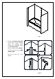
Detailed Diagram of Shower Door/Tub Door Components 1 7 5 8 2 9 3 10 11 6 12 13 14 4 The glass surface with the ClearMax™ label must be installed to face inside of the shower 15 Packing List 01 02 03 04 05 06 07 08 Upper guide rail Wall profile Glass profile - 1 Left / 1 Right Bottom guide rail Glass door Handle Wall anchor Pan head screw ST4.2×16 1pc 2pcs 2pcs 1pc 2pcs 2pcs 8pcs 16pcs 09 10 11 12 13 14 15 Truss head screw ST4.
Shower Door Installation 1. Measure the distance between the two finished walls at the top (at unit height), middle and bottom. The wall profiles will adjust for out-of-plumb conditions. Use the smallest measurement as the finished dimension. See Fig. 1 for details. Top Middle Bottom W Fig. 1 The Upper guide rail (#01) and the Bottom guide rail (#04) have been pre-cut for your model width.
FINISHED OPENING - 2-1/4" = FINISHED CUT LENGTH "D" Upper Guide Rail "D" EQ CUT BOTTOM RAIL EQUALLY FROM BOTH ENDS "D" "D" Bottom Guide Rail EQ Fig. 2 3. Secure Upper guide rail (#01) and Bottom guide rail (#04) to the Glass profiles (#03) with the Truss head screws ST4.2×16 (#15). 1 3 1 3 inside inside See Fig. 3 and Fig. 4 for details. outside Note: There are 3 holes in the top end of the glass profiles.
Fig. 4 4. Push the Glass Profiles (#03) all the way over the Wall Profiles (#02). Make sure the Wall Profile flange faces inside the shower. 1 inside See Fig. 5 and Fig. 6 for details. 2 Fig. 5 DUET manual Ver.
Fig. 6 5. Move the assembled frame to the designated position and adjust the Wall profiles (#02) so that they are tight to the walls by slightly pulling them out of the Glass Profiles (#03) if necessary. NOTE: Use a level to check the wall profiles for plumb and vertical while marking the holes for drilling. See Fig. 7 for details. Fig. 7 DUET manual Ver.
1 6. Hold the frame in the correct position, mark the drill holes on the wall through the holes on the flange of the Wall Profile (#02). Set the assembled unit aside; drill the holes in the wall using a Ø5/16” drill bit and insert the Wall anchors (#07). 3 inside Ø 5/16” outside See Fig. 8 for details. 2 4 Fig. 8 7. Apply silicone to the back of the wall profiles, into the drilled holes and to the bottom of the bottom guide rail prior to attaching to the opening.
8. Secure the Rollers (#11) to the top of the Glass door (#05). Mind the direction of the rollers. (See Fig 10.1 and Figs 11- 13) Attach the Handle brackets (#12) to the Glass doors (A & B) using the 25mm machine head screws (screw bag #12). The handle brackets should face the same direction as the roller wheels. Then secure the Handles (#06) to the Handle brackets using Round head screw ST4.2×25 (screw bag #12) and cover the holes with the decorative bracket covers provided. (Fig 10.
B Fig. 12 9. From inside of the shower, install the outside Glass door (A) (#05) first, as shown in Fig 13.1 and 13.2. Then install the inside Glass door (B) (#05) making sure that the rollers are aligned in the Upper guide rail (#01) as shown. See Fig. 13 and Fig. 14 for details. 1 outside 3 inside B A 2 4 Fig. 13 DUET manual Ver.
Fig. 14 10. From inside the shower, slide both Glass Doors (#01) to the right. Place the Left guide block (#13) to the end of the guide rail and mark the drill hole in the Bottom Guide rail (#04) through the pre-drilled hole on the block using an Ø1/8” drill bit. Drill the hole and secure the Guide block with the Pan Head screw ST4.2×16 (08) using the washers and the Decorative Covers (10). See fig. 15 for details.
11. Fasten the Rubber stopper (#14) inside the groove of the Wall Profile (#02) using the Pan Head screw ST4.2×16 (#08). Repeat for all 6 of the Rubber stoppers (#14). 1 See Fig. 16 for details. 2 Fig. 16 12. Perform final adjustments of the Wall Profiles (#02) on the assembled unit making sure that the bottom rail is tight to the threshold. Drill Ø1/8" holes through the Glass profiles (#03) into the Wall profiles (#02) as shown in Fig 18.1 and attach them together using the Pan Head ST4.
13. After final adjustments of the Glass doors (#05), install the small black Pin Blocker that is packaged with the Rollers (#11). Insert the Pin Blockers all the way into the pre-drilled holes on the body of the Roller from the screw side as shown. This pin will prevent the doors from being lifted of the track, See Fig. 18 for details. Fig. 18 14.
Product Maintenance BASES and BACKWALLS: To ensure long lasting life for your acrylic back walls: wipe them off after each use with a soft cloth. To clean the acrylic back walls use nonabrasive sprays or cream based cleaners. Avoid the use of aerosol spray cleaners. Never use abrasive cleansers, metal brushes or scrapers that could scratch or dull the surface. GLASS: To ensure long lasting life for your glass shower products: wipe them off after each use with a soft cloth.
TEL: 866-731-2244 FAX: 866-857-3638 DREAMLINE.COM For more information on DreamLine® Shower Doors and Enclosures please visit DreamLine.