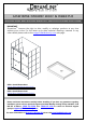
Charisma Shower Door & Base Kit SHOWER Door AND SHOWER BASE KIT INSTALLATION INSTRUCTIONS IMPORTANT DreamLineTM reserves the right to alter, modify or redesign products at any time without prior notice. For the latest up-to-date technical drawings, manuals or any other details please refer to the support.BathAuthority.com web page.
CHARISMA SHOWER/TUB DOOR INSTALLATION INSTRUCTIONS IMPORTANT DreamLineTM reserves the right to alter, modify or redesign products at any time without prior notice. For the latest up-to-date technical drawings, manuals or any other details please refer to the support.BathAuthority.com web page. Please read these instructions carefully before installing.
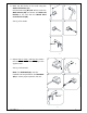
Preparation 1. After opening all boxes and packages, read this introduction carefully. Check that all of the needed parts are included in the package, by marking all the components on the “Detailed Diagram of Shower/Tub Door Components”. Examine boxes and packages for shipping damage. If the unit has been damaged, has a finishing defect, or has missing parts, please contact our customer support department within 5 business days of the delivery date.
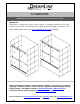
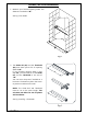
Detailed Diagram of Shower/Tub Door Components 5 1 6 3 7 8 9 4 10 11 12 2 13 14 15 16 17 Packing List 01 02 03 04 05 06 07 08 09 Guide rail Threshold Glass door Handle Wall anchor Round head screw ST4.2×16 Round head screw ST4.2×25 Round head screw ST4.
Shower/Tub Door Installation 1. Measure your finished opening width. This distance is marked as “W”. See Fig. 1 for details. Fig. 1 2. The Guide rail (01) and the Threshold (02) have been precut for an opening width of 60”. If your finished opening width is less than 60”, you will need to cut the Guide rail and the Threshold to the size of “W”. You can use a chop saw if available or a hack saw. File down any burrs that occur to prevent scratches on the wall.
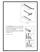
W W Fig. 3 3. If the Threshold (02) has been cut off, the pre-drilled hole may be shifted. In this case you will need to drill another hole. Drill the hole from the top, 1-1/2” away from the end of the Threshold. Drill through both layers of aluminum using Ø3/16” drill bit, and then enlarge the hole of the first layer with Ø5/16” drill bit. 1 1/2″ 1 See Fig. 4 for details. Ø 3/16” 2 3/4” Ø 5/16” 3 Fig. 4 Ver. 2, Rev.
4. Place the Threshold (02) in the desired position and parallel to the front edge of the Shower base or the Tub. Measure the distance from the front edge of the Threshold to the far corner of the wall. This distance is “X”. (you will need this distance for Step 6) Mark the drill holes through the predrilled holes at both ends of the Threshold. X See Fig. 5 for details. Fig. 5 5. Drill the holes in the Shower base or the Tub using Ø 1/8” drill bit.
Height of the Guide Rail Bracket for Shower door. 6. Place your Guide Rail Bracket (11) at a height of 69-1/4” from the base and at dimension “X” from the back wall (from Step 4). Even front bottom corner of the Guide Rail Bracket with the outside of the Threshold (02) to mark the wall for drilling. Be sure to keep the Guide Rail Bracket level. X X 69 1/4” See Fig. 7 for details. Fig. 7 Height of the Guide Rail Bracket for Tub door. 7.
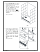
8. Mark the drill holes on the wall using the Guide rail bracket (11). Drill the holes using Ø 5/16” drill bit, insert the Wall anchors (05) and secure the Guide rail bracket to the wall with the Round head screw ST4.2×35 (08). See Fig. 9 for details. 1 4 2 5 3 Ø5/16" Fig. 9 9. Repeat Step 6 / Step 7 and Step 8 to mount the second Guide rail bracket (11) to the opposite wall. 1 4 2 5 See Fig. 10 for details.
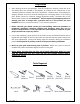
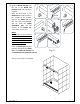
. Bring the Guide rail (01) over the top of the Guide rail brackets (11) and lock them together. Mark the drill holes in the Guide rail through the hole in the middle of the bracket. Remove the Guide rail and drill the holes using Ø 1/8” drill bit. Slide the Roller assemblies (10) into the channel of the Guide rail. (Two rollers in each slot).
. Secure the Glass doors (03) onto the Roller assemblies (10) and fasten them with the provided bolts. Attach the Handle brackets (12) onto the Glass doors. Attach Handles (04) to the Handle brackets. 1 4 2 5 3 6 See Fig. 13 and Fig. 14 for details. Fig. 13 NOTICE: On the outside Glass door, the Handle must be installed outwards. On the inside Glass door, the Handle must be installed inwards. Fig. 14 Ver. 2, Rev.
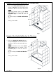
. Slide the Glass doors (03) to the right side and secure the Left Guide block (13) to the left end of the Threshold (02). Drill the holes into the Threshold through predrilled holes in the Guide block and fasten the Guide Block with the Round head screw ST4.2×16 (06). Slide the Middle Guide block (13) off the left edge of the Glass doors and secure it to the center of the Threshold. Drill the holes into the Threshold using Ø 1/8” drill bit and fasten the Guide block to it using Round head screw ST4.
Caulk Fig. 17 Product Maintenance To ensure long lasting life for your acrylic back walls, wipe them off after each use with a soft cloth. To clean the acrylic back walls use non-abrasive sprays or cream based cleaners. Never use abrasive cleansers, metal brushes or scrapers that could scratch or dull the surface. To ensure long lasting life for your glass shower products, wipe them off after each use with a soft cloth.
SLIMLINE SHOWER BASE SHOWER BASE DIMENSIONS AND INSTALLATION INSTRUCTIONS IMPORTANT DreamLineTM reserves the right to alter, modify or redesign products at any time without prior notice. For the latest up-to-date technical drawings, manuals or any other details please refer to the support.BathAuthority.com web page. Please read these instructions carefully before installing.
Preparation 1. Examine boxes and packages for shipping damage. Carefully remove Shower base from the packaging and check for any visual defects or shipping damages. If the unit has been damaged, has a finishing defect, or has missing parts, please contact our customer support department within 5 business days of the delivery date. Please note that DreamLineTM will not replace any damaged products or missing parts free of charge after 5 business days or if the product has been installed.
SINGLE THRESHOLD SHOWER BASE Center Drain Configuration W W1 D1 D MODEL SPECIFICATION D (in) W (in) D1 (in) W1 (in) DLT-1132320 DLT-1136360 DLT-1136480 DLT-1130600 DLT-1132600 DLT-1134600 DLT-1136600 32"×32" 36"×36" 36"×48" 30"×60" 32"×60" 34"×60" 36"×60" 32" 36" 36" 30" 32" 34" 36" 32" 36" 48" 60" 60" 60" 60" 16" 15" 15" 15" 15" 15" 15" 16" 18" 24" 30" 30" 30" 30" “SLIMLINE SHOWER BASE” Rev.3 Ver.
Left-Hand Drain Configuration W W1 D1 D MODEL SPECIFICATION D (in) W (in) D1 (in) W1 (in) DLT-1130601 DLT-1132601 DLT-1134601 DLT-1136601 30"×60" 32"×60" 34"×60" 36"×60" 30" 32" 34" 36" 60" 60" 60" 60" 15" 15" 17" 18" 12" 12" 12" 12" “SLIMLINE SHOWER BASE” Rev.3 Ver.
Right-Hand Drain Configuration W W1 D1 D MODEL SPECIFICATION D (in) W (in) D1 (in) W1 (in) DLT-1130602 DLT-1132602 DLT-1134602 DLT-1136602 30"×60" 32"×60" 34"×60" 36"×60" 30" 32" 34" 36" 60" 60" 60" 60" 15" 15" 17" 18" 12" 12" 12" 12" “SLIMLINE SHOWER BASE” Rev.3 Ver.
NEO SHOWER BASE W C C A W B A MODEL SPECIFICATION W (in) A (in) B (in) C (in) DLT-2036360 DLT-2038380 DLT-2040400 DLT-2042420 36"×36" 38"×38" 40"×40" 42"×42" 36" 38" 40" 42" 18 5/16" 20 5/16" 22 5/16" 24 5/16" 25" 25" 25" 25" 12" 12" 14 3/8" 14 3/8" “SLIMLINE SHOWER BASE” Rev.3 Ver.
QUARTER ROUND SHOWER BASE W C C W R MODEL SPECIFICATION W (in) C (in) R (in) DLT-7033330 DLT-7036360 DLT-7038380 33"×33" 36"×36" 38"×38" 33" 36" 38" 12" 12" 12" 21 5/8" 21 5/8" 21 5/8" “SLIMLINE SHOWER BASE” Rev.3 Ver.
DOUBLE THRESHOLD SHOWER BASE Corner Drain Configuration W C C W MODEL SPECIFICATION W (in) C (in) DLT-1032320 DLT-1036360 32"×32" 36"×36" 32" 36" 12" 12" “SLIMLINE SHOWER BASE” Rev.3 Ver.
Left-Hand Drain Configuration W W1 D1 D MODEL SPECIFICATION D (in) W (in) D1 (in) W1 (in) DLT-1034481 DLT-1036481 DLT-1036601 34"×48" 36"×48" 36"×60" 34" 36" 36" 48" 48" 60" 17" 18" 18" 12" 12" 12" “SLIMLINE SHOWER BASE” Rev.3 Ver.
Right-Hand Drain Configuration W W1 D1 D MODEL SPECIFICATION D (in) W (in) D1 (in) W1 (in) DLT-1034482 DLT-1036482 DLT-1036602 34"×48" 36"×48" 36"×60" 34" 36" 36" 48" 48" 60" 17" 18" 18" 12" 12" 12" “SLIMLINE SHOWER BASE” Rev.3 Ver.
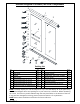
Diagram of the Shower Base in a Cross Section Cement board Finished Wall Shower Base (2"×4") Stud Mortar/Plaster Drain “SLIMLINE SHOWER BASE” Rev.3 Ver.
Shower Base Installation Preparation 1. Ensure that the floor and the studs are at right angle. Provide a 5”×5” opening in the subfloor for the drain. The 2” PVC waste pipe should extend above the surface of the sub-floor according to the drain installation instructions and the height of the Shower base. Refer to the product drawings in these installation instructions for the drain location. 90° 90° 90° See Fig. 1 and Fig. 2 for details.
2. Install the shower drain (NOT PROVIDED) according to the drain installation manual (supplied with the drain). See Fig. 3 for details. Fig. 3 3. Place the tray into the designated position so that the Drain Body drops around the Drain Pipe and butt the Shower Base up against the studs. See Fig. 4 for details. Lift and lower base over the center of The drain pipe and set it into the place Fig. 4 “SLIMLINE SHOWER BASE” Rev.3 Ver.
4. Level the tray and place marks on the studs above the upper edge of the tile flange. See Fig. 5 for details. Level base in two directions Fig. 5 5. Mix the bedding material (Mortar, Plaster, etc). Concrete is not recommended. Apply enough bedding material to support the entire bottom of the shower base. See Fig. 6 for details. Mortar/Plaster Fig. 6 “SLIMLINE SHOWER BASE” Rev.3 Ver.
6. After the bedding material has been poured and before it sets, place the shower base into the position with the drain assembly sliding over the PVC waste pipe. It will be necessary to push the shower base until the top of the tile flange aligns with the marks drawn on the studs and the front edge is contacting the rough floor along the entire length of the shower base. Ensure that the base is level in all directions.
Fig. 9 Product maintenance To insure long lasting life for your acrylic back walls, wipe them off after each use with a soft cloth. To clean the acrylic back walls use non-abrasive sprays or cream based cleaners. Never use abrasive cleansers, metal brushes or scrapers that could scratch or dull the surface. To insure long lasting life for your glass shower products, wipe them off after each use with a soft cloth. Rinse and wipe of the glass using either soft cloth or squeegee to prevent soap buildup.
DREAMLINE™ EXCLUSIVE LIMITED WARRANTY AS OF MAY 6, 2013 This warranty extends only to the original owner/end‐user for household use only and is not transferable to a subsequent owner. This warranty extends for a designated period of time, so long as it remains in use in its original place of installation. This warranty applies only to DreamLine products purchased from an authorized dealer in United States or Canada.
TEL: 866-731-2244 FAX: 866-227-1533 WWW.BATHAUTHORITY.COM For more information on DreamLineTM Shower Doors please visit www.BathAuthority.