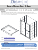
Encore Shower Door & Base SHOWER DOOR & BASE INSTALLATION INSTRUCTIONS IMPORTANT DreamLine® reserves the right to alter, modify or redesign products at any time without prior notice. For the latest up-to-date technical drawings, manuals, warranty information or additional details please refer to your model’s web page on DreamLine.
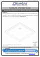
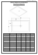
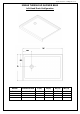
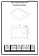
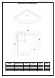
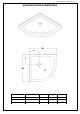
©2018 DreamLine. All Rights Reserved SLIMLINE SHOWER BASE SHOWER BASE DIMENSIONS AND INSTALLATION INSTRUCTIONS IMPORTANT! DreamLine® reserves the right to alter, modify or redesign products at any time without prior notice. For the latest up-to-date technical drawings, manuals, warranty information or additional details please refer to your model’s web page on DreamLine.
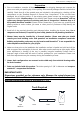
©2018 DreamLine. All Rights Reserved Preparation 1. Prior to installation, examine all boxes and packages for shipping damage and compare the piece count with your packing slip. After opening all boxes and packages read this introduction carefully. Check that all of the needed parts are included in the package by checking off the components on the “Detailed Diagram of Shower Door Components”.
©2018 DreamLine.
©2018 DreamLine.
©2018 DreamLine.
©2018 DreamLine.
©2018 DreamLine.
©2018 DreamLine.
©2018 DreamLine.
©2018 DreamLine.
©2018 DreamLine.
©2018 DreamLine.
©2018 DreamLine.
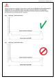
©2018 DreamLine. All Rights Reserved Shower Base Installation - Preparation 1. Ensure that the floor and the studs are at right angles. Provide a 5”×5” opening in the subfloor for the drain. The 2” PVC waste pipe should extend above the surface of the sub-floor according to the drain installation instructions and the height of the Shower base. Refer to the product drawings and tables in this installation manual for the drain location. 90° 90° 90° See Fig. 1 and Fig. 2 for details.
©2018 DreamLine. All Rights Reserved 2. Install the shower drain (NOT INCLUDED) according to the drain installation manual (supplied with the drain). See Fig. 3 for example Fig. 3 3. Place the tray into the designated position so that the Drain cutout drops around the Drain Pipe and butt the Shower Base up against the studs. See Fig. 4 for details. Lower the base over the drain pipe and set it into place against the studs. Fig.
©2018 DreamLine. All Rights Reserved 4. Level the tray and place marks on the studs above the upper edge of the tile flange. See Fig. 5 for details. Level base in two directions Fig. 5 5. Mix the bedding material (Mortar, cement-sand mix, etc.) Concrete or plaster is not recommended. Apply enough bedding material to support the entire bottom of the shower base. This will add additional stability and prevent the base from shifting position. See Fig. 6 for details. Mortar Fig.
©2018 DreamLine. All Rights Reserved 6. After the bedding material has been poured and before it sets, place the shower base into the position with the drain assembly sliding over the PVC waste pipe. It will be necessary to push the shower base until the top of the tile flange aligns with the marks drawn on the studs and the front edge is contacting the rough floor along the entire length of the shower base. Ensure that the base is level in all directions.
©2018 DreamLine. All Rights Reserved Fig.
©2018 DreamLine. All Rights Reserved Product Maintenance BASES and BACKWALLS: To ensure long lasting life for your acrylic base and/or back walls: wipe them off after each use with a soft cloth. To clean the acrylic base or back walls use non-abrasive sprays or cream based cleaners. Avoid the use of aerosol spray cleaners. Never use abrasive cleansers, metal brushes or scrapers that could scratch or dull the surface.
TEL: 866-731-2244 FAX: 866-857-3638 DREAMLINE.COM For more information on DreamLine® Shower Doors and Enclosures please visit DreamLine.
ENCORE d SHOWER AND TUB DOOR INSTALLATION ne veINSTRUCTIONS i r L e s m e a R e r s D ght © Ri All IMPORTANT DreamLine® reserves the right to alter, modify or redesign products at any time without prior notice. For the latest up-to-date technical drawings, manuals, warranty information or additional details please refer to your model’s web page on DreamLine.com MODEL #s http://dreamline.
d e e n v i r L e s m e a R e r s D ght © Ri All This model is treated with DreamLine’s exclusive ClearMaxTM Glass technology. This is a specially formulated coating that prevents the build up of soap and water spots. d e e n erv i L For best results, squeegee the glass after s m e a each usee and dry with R a soft cloth. r s D ght © Ri All ENCORE shower and tub door manual Ver 1 Rev 5 05/2018 ©2018 DreamLine.
Table of Contents Section title Page # Preparation Tools 2 Cutting the guide rails Installing the doors 4 5-16 6 13-14 Roller Assembly Adjustment 15 Product maintenance 17 d e e in erv L s m e a R e r s D ght © Ri All ! All drawings in this manual are for illustrative purposes only and are not drawn to scale. ENCORE / BRAVO Manual Ver 1 Rev 5 10/2017 ©2017 DreamLine.
Preparation 1. Prior to installation, examine all boxes and packages for shipping damage and compare the piece count with your packing slip. After opening all boxes and packages read this introduction carefully. Check that all of the needed parts are included in the package by checking off the components on the “Detailed Diagram of Shower Door Components”.
Tools Silicone 1” thick wood block Phillips Screwdriver Pencil Drill bit (Ø5/16") d e e n v i r L e s m e a R e r s D ght © Ri All Metal File Power Drill Professional-grade Glass suction cup Hammer Painter’s Tape Drill bit (Ø1/8") Miter Saw or Hacksaw Work Gloves Safety Glasses Top Tip: Measure the finished opening before proceeding with the installation to be sure that the correct model size has been ordered. d e e in erv L s m e a R e r s D ght © Ri ! All Threshold must be level.
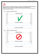
Detailed Diagram of shower door components 4 1 2 3 5 7 8 9 d e 3e n v i r L e s 1 m e a R e r s D ght © Ri All 10 For models with frosted glass: install the textured surface toward the outside of the shower.
Installation steps NOTE: This manual will describe the shower door installation. Follow the same sequence of installation steps for the tub door installation. d e e n v i r L e s m e a R e r s D ght © Ri All 1. Check the threshold for level and the walls for plumb. Measure the finished opening width at the bottom and at the top (at the model height: 58’’ for tub or 76” for shower). Use these dimensions as “Wtop” and “Wbot”in step #2. Check the threshold for level and the walls for plumb.
2. Use a miter saw or hacksaw to cut the Upper Guide Rail (#02) 1/16” shorter than the top dimension Wtop from step #1. (Wtop - 1/16“ = finished cut length L) (Fig 2a) The Bottom Guide Rail (#15) needs to be cut equally from both ends to keep the center guide holes centered. (The Bottom Guide Rail (#15) has been precut for the model size. See Table A). Using a miter saw or hack saw, cut the Bottom Guide Rail (#15) 3/4” shorter than the bottom dimension Wbot from step #1.
3. Place the Bottom Guide Rail (#15) onto the threshold in the desired position. Use a tape measure to align the Bottom Guide Rail (#15) parallel with the front edge of the threshold and mark its position. (Fig 3a) ! TIP: Use the left and right Wall Profiles (#01) to center the Bottom Guide Rail (#15) on the threshold to maintain the proper spacing from the walls. (Fig 3b) d e e n v i r L e s m e a R e r s D ght © Ri All d e e in erv L s m e Fig 3a a R e r s D ght © Ri All ©2018 DreamLine.
4. Attach the Upper Guide Rail Connectors (#07) to one end of both Wall Profiles (#01) using the ST4.2 x 30 Truss Head Screws (#13). (Fig 4a) Position one Wall Profile (#01) against the wall tight to the threshold and over the Bottom Guide Rail (#15). Check for plumb with a level and mark the position. Mark both holes for drilling on the wall through the holes in the Upper Guide Rail Connector (#07). (Fig 4b) Remove the wall profile and drill Ø5/16” holes and insert the Wall Anchors (#09).
5. Apply silicone to the back of the Wall Profile (#01) and place it back onto the marked position on the wall. Attach the Upper Guide Rail Connector (#07) to the wall using two each of the ST4.2 x 40 Countersunk Flathead Screws (#10). Attach two of the Wall Profile Bumpers (#04) using the ST4.2 x 10 Screws (#11) and cover the holes with the decorative caps.
6. Position the Bottom Guide Rail (#15) back onto the threshold and mark the threshold through the Guide Block (#05) holes for drilling. Remove the Bottom Guide Rail (#15) and drill into the threshold: ◾Drill Ø1/8” holes for installation into an acrylic threshold ◾Drill Ø5/16” holes and use anchors for installation into a tile threshold. (Fig 6) d e e n v i r L e s m e a R e r s D ght © 2 i R All 1 Ø1/8” or Ø5/16” ! The bottom rail must be screwed to the threshold or tub deck.
8. Position the opposite Wall Profile (#01) against the wall, tight to the threshold and over the Bottom Guide Rail (#15). Check for plumb with a level and mark the position. Mark the holes in the Upper Guide Rail Connector (#07) for drilling. (Fig 8b.1) Remove the wall profile and drill Ø5/16” holes and insert the Wall Anchors (#09). (Fig 8a and 8b) d e e n v i r L e s m e a R e r s D ght © Ri All Fig 8a ©2018 DreamLine.
9. Apply silicone to the back of the Wall Profile (#01) and place it back onto the marked position on the wall. Attach the Upper Guide Rail Connector (#07) to the wall using two each of the ST4.2 x 40 Countersunk Flathead Screws (#10). Attach two of the Wall Profile Bumpers (#04) using the ST4.2 x 10 Screws (#11) and cover the holes with the decorative caps.
NOTE: Do Not attach the Towel Bars (#08) to the Door Glass (#03) until instructed. Do Not attempt to lift the glass with the towel bars. This may cause damage to the glass and/or serious personal injury. Use an assistant and/or a professional grade glass suction cup to handle the glass. ! d e e n v i r L e s m e a R e r s D ght © Ri All 11. Install the Roller Assemblies (#06) onto the tops of both doors.
13. Use an assistant to support the Upper Guide Rail (#02). Line the rollers up with the notches in the anti-jump fins inside the guide rail and lift and insert the outer door glass up into the Upper Guide Rail (#02) so the Roller Assemblies (#06) fit onto the groove inside the rail. Carefully lower the Upper Guide Rail (#02) so the door glass slides into the outer slot in the Guide Block (#05).
15. To compensate for minor out-of-plumb conditions Cover plate / Mounting bolt (up to 3/8”): After both doors are installed, use the Allen Wrench (#14) to make minor adjustments with the Adjustment bolts on the Roller Assemblies (#06). Remove the cover plate, then loosen the mounting bolt on the roller. Rotate the adjustment bolt on the bottom of the wheel assembly to tilt the door glass to the desired position. Re-tighten the mounting bolt and replace the cover plate.
17. Apply good quality mildew-resistant silicone to the entire interior perimeter where the wall profiles meet the wall and along the bottom guide rail and threshold. (Fig 17) ! Allow 24 hours for the silicone to cure before using the shower. d e e n v i r L e s m e a R e r s D ght © Ri All 24 Hours ©2018 DreamLine.
Product Maintenance BASES and BACKWALLS: To ensure longlasting life for your acrylic back walls: wipe them off after each use with a soft cloth. To clean the acrylic back walls use non-abrasive sprays or cream based cleaners. Avoid the use of aerosol spray cleaners. Never use abrasive cleansers, metal brushes or scrapers that could scratch or dull the surface.
TEL: 866-731-2244 FAX: 866-857-3638 DREAMLINE.COM For more information on DreamLine® Shower Doors and Enclosures please visit DreamLine.com ©2018 DreamLine.