Flex Shower Door, Base & Q-Wall 5.2 SHOWER DOOR, BASE & BACKWALL INSTALLATION INSTRUCTIONS IMPORTANT DreamLine® reserves the right to alter, modify or redesign products at any time without prior notice. For the latest up-to-date technical drawings, manuals, warranty information or additional details please refer to your model’s web page on DreamLine.
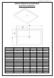
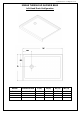
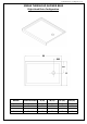
©2018 DreamLine. All Rights Reserved SLIMLINE SHOWER BASE SHOWER BASE DIMENSIONS AND INSTALLATION INSTRUCTIONS IMPORTANT! DreamLine® reserves the right to alter, modify or redesign products at any time without prior notice. For the latest up-to-date technical drawings, manuals, warranty information or additional details please refer to your model’s web page on DreamLine.
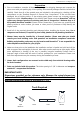
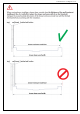
©2018 DreamLine. All Rights Reserved Preparation 1. Prior to installation, examine all boxes and packages for shipping damage and compare the piece count with your packing slip. After opening all boxes and packages read this introduction carefully. Check that all of the needed parts are included in the package by checking off the components on the “Detailed Diagram of Shower Door Components”.
©2018 DreamLine.
©2018 DreamLine.
©2018 DreamLine.
©2018 DreamLine.
©2018 DreamLine.
©2018 DreamLine.
©2018 DreamLine.
©2018 DreamLine.
©2018 DreamLine.
©2018 DreamLine.
©2018 DreamLine.
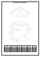
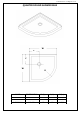
©2018 DreamLine. All Rights Reserved Shower Base Installation - Preparation 1. Ensure that the floor and the studs are at right angles. Provide a 5”×5” opening in the subfloor for the drain. The 2” PVC waste pipe should extend above the surface of the sub-floor according to the drain installation instructions and the height of the Shower base. Refer to the product drawings and tables in this installation manual for the drain location. 90° 90° 90° See Fig. 1 and Fig. 2 for details.
©2018 DreamLine. All Rights Reserved 2. Install the shower drain (NOT INCLUDED) according to the drain installation manual (supplied with the drain). See Fig. 3 for example Fig. 3 3. Place the tray into the designated position so that the Drain cutout drops around the Drain Pipe and butt the Shower Base up against the studs. See Fig. 4 for details. Lower the base over the drain pipe and set it into place against the studs. Fig.
©2018 DreamLine. All Rights Reserved 4. Level the tray and place marks on the studs above the upper edge of the tile flange. See Fig. 5 for details. Level base in two directions Fig. 5 5. Mix the bedding material (Mortar, cement-sand mix, etc.) Concrete or plaster is not recommended. Apply enough bedding material to support the entire bottom of the shower base. This will add additional stability and prevent the base from shifting position. See Fig. 6 for details. Mortar Fig.
©2018 DreamLine. All Rights Reserved 6. After the bedding material has been poured and before it sets, place the shower base into the position with the drain assembly sliding over the PVC waste pipe. It will be necessary to push the shower base until the top of the tile flange aligns with the marks drawn on the studs and the front edge is contacting the rough floor along the entire length of the shower base. Ensure that the base is level in all directions.
©2018 DreamLine. All Rights Reserved Fig.
©2018 DreamLine. All Rights Reserved Product Maintenance BASES and BACKWALLS: To ensure long lasting life for your acrylic base and/or back walls: wipe them off after each use with a soft cloth. To clean the acrylic base or back walls use non-abrasive sprays or cream based cleaners. Avoid the use of aerosol spray cleaners. Never use abrasive cleansers, metal brushes or scrapers that could scratch or dull the surface.
TEL: 866-731-2244 FAX: 866-857-3638 DREAMLINE.COM For more information on DreamLine® Shower Doors and Enclosures please visit DreamLine.
QWALL – 5.2 (2 Back Panels) SHOWER ACRYLIC WALL INSTALLATION INSTRUCTIONS IMPORTANT DreamLineTM reserves the right to alter, modify or redesign products at any time without prior notice. For the latest up-to-date technical drawings, manuals or any other details please refer to your model’s web page on BathAuthority.com Please read these instructions carefully before installing.
Preparation 1. Prior to installation, examine all boxes and packages for shipping damage and compare the piece count with your packing slip. After opening all boxes and packages read this introduction carefully. Check that all of the needed parts are included in the package by checking off the components on the “Detailed Diagram of Acrylic Shower Wall Components”.
Detailed Diagram of Acrylic Shower Wall Components 2 1 46 58 "- 50 "- 6 " 2" 3 4 5 6 10 7 8 9 Packing List 01 Side panel 2pcs 06 Wall anchor 21pcs 02 Corner cover 2pcs 07 Countersunk screw ST4.2×40 21pcs 03 Decorative edge molding 2pcs 08 Decorative cover 15pcs 04 Shelf bracket 6pcs 09 Back panel 2pcs 05 Glass shelf 2pcs 10 Center cover 1pc NOTE: Unpack your unit carefully and inspect it.
Preparation for Installation of Back Panel 1. Place a mark on the walls at a distance of 1” (one inch) from the corner and draw a plumb vertical line from top to bottom. 1 1" See Fig. 1 for details. NOTE: Repeat this step for both corners. 2 1" Fig. 1 2. The Shower back wall kit has two Back Panels (09). Measure the back wall of the shower between the vertical lines you marked in Step 1. This distance is marked as “W”. W See Fig. 2 for details. Fig. 2 Q-Wall 5.2 (w/two back panels) manual Ver.
3. Divide the measurement “W” by two and place a mark in the center of the back wall and from there draw a plumb vertical line from top to bottom. W/ 2 W/ 2 This distance is shown as “W/2”. See Fig. 3 for details. Fig. 3 4. Determine the position of both Back panels (09).
5. Measure the Back Panel (09). Width of the Back Panel has to be less than or equal to the distance between the center line and the corner line on the back wall in Step. 3 L ≤ W/2 L L If the width of the Back Panel is greater than the distance between the center line and the corner line on the back wall in Step. 3, you have to trim the Back Panel to fit your measurement. See Fig. 5 for details. Fig. 5 6.
7. Place the Back Panel (09) onto a flat piece of plywood or particle board. Use a sharp industrial knife and a T-square to score along the marked side ends of the Back panel and continue scoring until you have fully cut through the panel. See Fig. 7 and Fig. 8 for details. 1 2 Fig. 7 W/ 2 W/ 2 Fig. 8 Q-Wall 5.2 (w/two back panels) manual Ver. 1 Rev.
Preparation for Installation of Side Panels ATTENTION: If you are installing a shower door with a wall profile, you can hide the edge of the Side panel (01) behind the wall profile. Side Panel 1 Wall Profile Wall See Fig. 9 for details. Side Panel 2 Wall Profile Wall Fig. 9 8. Measure the side walls of the shower from the 1” (one inch) line in the corner (from Step. 1) to the distance where you want Side panels (01) to end. The distance is “D”. D D See Fig. 10 for details. Fig. 10 Q-Wall 5.
9. Determine the position of both Side panels (01). NOTE: a) The narrow edge of the Side panel fits behind the corner cover and cannot be trimmed. b) The wide edge of the Side panel can be trimmed to the size of your measurements from Step. 8. D D Line to cut Line to cut Measure from the narrow edge of the Side panel and place a mark at a distance of "D" (that you measured in Step. 8). Draw a straight line from top to bottom along the wide edge of the Side panel. See Fig. 11 for details. Fig. 11 10.
D D Fig. 13 11. Take exact measurements of the fixture on the wall: • • 1" D A from the 1” (one inch) line in the corner of the shower to the fixture: (A, B, C) from the bottom of the wall of the shower to the fixture: (E, F). See Fig. 14 for details. C E B F Fig. 14 Q-Wall 5.2 (w/two back panels) manual Ver. 1 Rev.
12. Determine which Side panel (01) will be installed on the side wall with the fixture. Mark the fixture location on the Side panel according to the measurements taken in Step. 11. A D See Fig. 15 for details. E F B C Fig. 15 13. Drill the holes for the fixtures in the Side panel (01) using the proper diameter saw bit or a handheld jig saw. D See Fig. 16 for details. Fig. 16 Q-Wall 5.2 (w/two back panels) manual Ver. 1 Rev.
Acrylic Back Panel and Side Panel Installation Instruction 14. Attach the Center cover (10) vertically at the center point along the line (from Step. 3) and mark the drilling holes through the predrilled holes in the Center cover. Drill the holes using Ø5/16” drill bit and insert the Wall Anchors (06). 1 2 3 4 See Fig. 17 for details. Ø5/16" Fig. 17 15. Mount the Center cover (10) to the centerline of the back wall using the Countersunk screws ST4.2×40 (07).
W/ 2 W/ 2 Fig. 19 16. Attach the Corner cover (02) to the corner of the shower and mark the drilling holes through the predrilled holes in the Corner cover. Move aside the Corner cover, Drill the holes using Ø5/16” drill bit and insert the Wall Anchors (06). See Fig. 20 and Fig. 21 for details 1 2 3 4 Ø5/16" Fig. 20 Q-Wall 5.2 (w/two back panels) manual Ver. 1 Rev.
W/ 2 W/ 2 Fig. 21 ATTENTION: Installation of all Acrylic panels must be finished before the sealant sets for easy leveling and adjustments. W/ 2 W/ 2 17. Apply the sealant to the entire surface of the reverse side of the Back panel (09). See Fig. 22 for details. Fig. 22 Q-Wall 5.2 (w/two back panels) manual Ver. 1 Rev.
1 18. Slide the right edge of the left Back panel (09) all the way behind the Center cover (10) and push the Back panel against the wall. Slide the left edge of the right Back panel (09) all the way behind the Center cover (10) and push the Back panel against the wall as well. You can adjust the position of the Back panels before the sealant sets. Apply equal pressure to the whole surface of the Back panels from top to bottom. 2 See Fig. 23 and Fig. 24 for details. 3 Fig. 23 Fig. 24 Q-Wall 5.
19. Mount the Corner cover (02) to the corner of the shower using the Countersunk screws ST4.2×40 (07). Do not fully tighten the screws at this time; leave them loose for further installation. See Fig. 25 for details 1 2 3 4 Fig. 25 20. Apply the sealant to the entire surface of the reverse side of the Side panel (01). Also, apply the sealant around the drilled holes. See Fig. 26 for details. Fig. 26 Q-Wall 5.2 (w/two back panels) manual Ver. 1 Rev.
21. Slide the narrow edge of the Side panel (01) behind the Corner cover (02). Align trimmed edge of the Side panel (from Step. 9) with the marked line on the wall (in Step. 7) and push the Side panel against the wall. NOTE: Make sure the drilled holes on the Side panel are also aligned with the fixtures on the wall. See Fig. 27 for details. 1 2 Fig. 27 22. Apply sealant to the entire surface of the reverse side of the other Side panel (01). See Fig. 26 for details.
23. Once all panels are aligned, fasten tight the Corner cover (02) to secure the Side panels (01) and Back panels (09). Cover the screw holes with the Decorative covers (08). 1 See Fig. 29 for details. 2 Fig. 29 1 24. Fasten tight the Center cover (10) to secure the Back panels (09). Cover the screw holes with the Decorative covers (08). See Fig. 30 for details. 2 Fig. 30 Q-Wall 5.2 (w/two back panels) manual Ver. 1 Rev.
ATTENTION; Prior to the next step, please be sure the part of the wall for installation of the Decorative edge molding (03) is clean, dry and free from soap, oil and any construction debris. 25. Gently remove the plastic tape from the adhesive side of the Decorative edge molding (03) and firmly press it to the edge of the Side panel (01) from top to bottom. See Fig. 31 for details. 1 Side Panel Wall Decorative Molding 2 Side Panel Wall Decorative Molding Fig. 31 26.
Glass Shelves Installation Instruction 27. Determine the desired height for the Glass shelves (05) and mark the locations on the wall. NOTE: The Glass shelves can be installed either two in one corner, or one in each. See Fig. 33 for details. G H ` Fig. 33 3 1/2" 28. Mark the location for the Shelf brackets (04) according to the measurements in Fig. 28 and Fig. 29.1. Drill the holes using Ø5/16” drill bit and insert the Wall anchors (06). See Fig. 34 for details. 3 1/2" 3 1/2" 1 Ø 5/16" 2 3 Fig.
1 29. Mount the Shelf brackets (04) to the wall using the Countersunk screws ST4.2×40 (07). NOTE: the padded set screw of the Glass bracket should be facing down. Slide the upper Glass shelf (05) into the upper Shelf brackets and tighten the set screws at the bottom of the brackets. Then slide the bottom Glass shelf in place. Tighten the set screws on the bottom Shelf brackets as well. 2 See Fig. 35 and Fig. 36 for details. 3 Fig. 35 Fig. 36 Q-Wall 5.2 (w/two back panels) manual Ver. 1 Rev.
Product maintenance To ensure long lasting life for your acrylic back walls, wipe them off after each use with a soft cloth. To clean the acrylic back walls use non-abrasive sprays or cream based cleaners. Never use abrasive cleansers, metal brushes or scrapers that could scratch or dull the surface. Acrylic cleaning procedure: Acrylic should be cleaned with warm water and a clean, non-abrasive cloth. If desired, a mild, non-abrasive detergent may also be used. Use only light pressure when cleaning.
TEL: 866-731-2244 FAX: 866-857-3638 WWW.BATHAUTHORITY.COM For more information on DreamLineTM Shower Back Wall please visit www.BathAuthority.com Q-Wall 5.2 (w/two back panels) manual Ver. 1 Rev.
FLEX 42”x 72“/ 48”x 72“/ 60”x 72” SHOWER DOOR INSTALLATION INSTRUCTIONS IMPORTANT DreamLine® reserves the right to alter, modify or redesign products at any time without prior notice. For the latest up-to-date technical drawings, manuals, warranty information or additional details please refer to your model’s web page on DreamLine.
Table of Contents Section title Preparation Tools Parts Diagram of Shower Door Components Parts List Page # 2 3 4 Model Overview 5 6 Installation Steps 7-19 Vinyl Seals 16-17 Product Maintenance 20 FLEX 42x72 / 48x72 / 60x72 manual Ver 1 Rev 3 04/2018 ©2018 DreamLine.
Preparation 1. Prior to installation, examine all boxes and packages for shipping damage and compare the piece count with your packing slip. After opening all boxes and packages read this introduction carefully. Check that all of the needed parts are included in the package by checking off the components on the “Detailed Diagram of Shower Door Components”.
Tools Level Drill bit (Ø=5/16") (8mm) Tape Measure Drill bit (Ø=1/8") (3mm) Phillips Screwdriver Pencil Power Drill Hammer Razor Knife 100% Silicone Top Tip: Measure the finished opening before proceeding with the installation to be sure that the correct model size has been ordered. Threshold must be level. Middle Tip: Prior to installation, cover the shower/tub drain with tape to prevent losing screws or small parts. ! W ©2018 DreamLine.
3 1 Parts Diagram 4 5 15 2 12 6 1 17 13 14 16 8 ©2018 DreamLine.
Parts List Part# DESCRIPTION QTY Part# DESCRIPTION QTY Wall profile 2pcs 12 Magnetic Strike Profile 1pc 2 Panel Glass assembly 1set 13 Handle 1pc 3 Wall anchor 8pcs 14 ST4.2×25 Round head screw 4pcs 4 ST4.2×10 Round head screw 10pcs 15 Top & Bottom pivot Rail 2pcs 5 ST4.2×40 Truss head screw 8pcs 16 Top & Bottom pivot Hardware 2pcs 6 Decorative cap and washer 10pcs 17 Door Glass 1pc 7 Flanged anti-water strip 1pcs 8 Bottom anti-water strip 1pc ©2018 DreamLine.
Model Overview Alluminum wall profile Stationary panel glass assembly Expandable rail Door Glass pa ne l Alluminum wall profile do or ©2018 DreamLine.
Installation steps 1. Insert the Top & Bottom Pivot Rails (#15) into the expandable rails of the Stationary panel Assembly (#02). (Fig 1) SHDR-22427200-01 and SHDR-22487200-01: Insert the end that is closer to the pivot hole SHDR-22607200-01: Insert the end that is farthest from the pivot hole top outside inside outside inside bottom Right hand door installation shown insert this end pivot hole pivot hole do or 23 -5/ 8” 60” model do or 23 ©2018 DreamLine.
2. Attach the Magnetic Strike Profile (#12) to the Top & Bottom Pivot Rails (#15) using four of the ST4.2 x 25 Round Head Screws (#14). (Fig 2) ins ide inside Fig 2 ! ©2018 DreamLine. All Rights Reserved TIP: Apply some wax or dish soap to the screws to make assembly easier and to prevent stripping the screws.
3. Slide both of the Wall Profiles (#01) over the frame assembly. Be sure that the flanges on the Wall Profiles (#01) face in towards the shower. (Fig 3) inside inside pa ne inside l do or are a 4. At this point, the entire assembly can be flipped top to bottom for either left or right hand door installation. However, the flanges on the wall profiles must face into the shower. (Fig 4) Fig 3 pa el pan ne ©2018 DreamLine.
5. Check the threshold of the finished opening to make sure that it is level. (This model does not allow for out-of-level adjustment) (Fig 5) 6. Place the assembly onto the threshold at the desired location and extend the expandable Top & Bottom Pivot Rails (#15) evenly. (Fig 6) Fig 5 1 Right hand door installation shown FLEX 42x72 / 48x72 / 60x72 manual Ver 1 Rev 3 04/2018 ©2018 DreamLine.
7. The opening for the door glass must be square. Measure the top and bottom of the door opening and adjust the Expandable Rails as necessary. Push the Wall Profiles (#01) tight to the walls to compensate for up to 1/2” out-of-plumb per wall. (Fig 7) ! Make sure that the Wall Profiles (#01) are also tight to the threshold and even with the top of the frame assembly. the d mus oor ope t be n squa ing re Fig 7 8. Check that the frame assembly is plumb inside ©2018 DreamLine.
9. Move the frame assembly aside and remove the Wall Profiles (#01). Drill the holes into the walls using a Ø5/16” (8mm) drill bit and insert the Wall Anchors (#03). (Fig 9) 1 3 Ø5/16” (8mm) 2 4 Ø5/16” (8mm) Fig 9 10. Apply a bead of silicone to the back of the Wall Profiles (#01) and the screw holes where the Wall Profiles (#01) will be installed. Attach the Wall Profiles (#01) to the wall using the ST4.2 x 40 Truss Head Screws (#05). Repeat this process for the opposite wall profile.
11. Place the assembly back onto the threshold and into the panel-side Wall Profile (#01) first. (Fig 11) Fig 11 12. Extend the Expandable Rails evenly so that the Magnetic Strike Profile (#12) goes into the opposite Wall Profile (#01) on the door-side of the opening. (Fig 12) 1 ©2018 DreamLine.
13. Check and adjust the door opening for square and make certain that the entire assembly is tight to the threshold. (Fig 13) the d mus oor ope t be n squa ing re Fig 13 14. Install the Top & Bottom Pivot Hardware (#16) into the pivot bushings in the Top & Bottom Pivot Rails (#15). (Fig 14) pivot pivot rotation sid e ©2018 DreamLine. All Rights Reserved out inside pivot bushing (pre-installed in the rails) ! Note: The pivots are packaged as a pair. Check the difference in the rotation direction.
! NOTE: DO NOT install the handle onto the door glass until instructed. DO NOT attempt to lift the glass using the handle. This could result in damage to the glass and/or serious personal injury. Always use an assistant or a professional grade glass suction cup when handling heavy glass. 15. Carefully install the Door Glass (#17) onto the Top & Bottom Pivot Hardware (#16). Make certain that all gaskets are in place to protect the glass. Cover the bolt with the decorative cap.
16. Trim the Bottom Anti-Water Strip (#08) to fit on both sides of the bottom pivot and attach both pieces to the bottom of the Door Glass (#17) (Fig 16) ! NOTE: Measure to the edge of the door and notch the Bottom anti-water strip (#08) with a razor knife to fit around the magnet strip, leaving the bottom deflector intact. Fig 16 do or (Fig 17) do or ©2018 DreamLine. All Rights Reserved 17. Attach the Handle (#13) to the Door Glass (#17).
18. Attach the Flanged Anti-Water Strip (#07) to the vertical edge of the Stationary Panel Glass (#02) with the flange facing into the shower. (Fig 18) inside pa ne l outside pa ne l ©2018 DreamLine.
1 19. Once all adjustments have been made, drill pilot holes from inside of the shower into the Top & Bottom Pivot Rails (#15) through the predrilled holes using an Ø1/8” drill bit. Ø1/8” (3mm) 2 ins ins ide ! ide NOTE: Do Not drill the rails throughout, only through the first layer. Ø1/8” (3mm) 3 Secure the Expanding rails using the Round Head Screws ST4.2×10 (#04) and the raised white washers. Cover the exposed screw heads and washers with the Decorative Caps (#06). (Fig 19) ST4.
21. Apply a good quality mildew-resitant silicone around the interior perimeter along both walls and the threshold. (Fig 21) ! Allow 24 hours for the silicone to cure before using the shower. ©2018 DreamLine.
Product Maintenance BASES and BACKWALLS: To ensure long-lasting life for your acrylic back walls, wipe them off after each use with a soft cloth. To clean the acrylic back walls use non-abrasive sprays or cream based cleaners. Avoid the use of aerosol spray cleaners. Never use abrasive cleansers, metal brushes or scrapers that could scratch or dull the surface. GLASS: To ensure long-lasting life for your glass shower products, wipe them off after each use with a soft cloth.
TEL: 866-731-2244 FAX: 866-857-3638 DREAMLINE.COM For more information on DreamLine® Shower Doors and Enclosures please visit DreamLine.com ©2018 DreamLine.