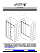
VISION SHOWER DOOR & TUB DOOR INSTALLATION INSTRUCTIONS IMPORTANT DreamLine reserves the right to alter, modify or redesign products at any time without prior notice. For the latest up-to-date technical drawings, manuals or any other details please refer to the support.BathAuthority.com web page. TM Please carefully read the instructions before installing.
Preparation 1. After opening all boxes and packages, read this introduction carefully. Check that all of the needed parts are included in the package, by marking all the components on the “Detailed Diagram of Shower Door Components”. Examine boxes and packages for shipping damage. If the unit has been damaged, has a finishing defect, or has missing parts, please contact our customer support department within 3 business days of the delivery date.
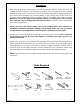
Detailed Diagram of Shower Door Components 10 9 8 7 3 2 1 11 12 5 13 4 14 6 15 16 17 Packing List 01 02 03 04 05 06 07 08 09 Glass profile Wall profile Guide rail Glass door Stationary glass Handle Magnetic strip Anti-water strip Single side strip 2pcs 2pcs 2pcs 2pcs 2pcs 2pairs 1pair 4pcs 2pcs 10 11 12 13 14 15 16 17 Round head screw ST4.2×30 Round head screw ST4.2x25 Round head screw ST4.2x10 Flat head screw ST4.
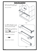
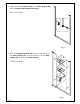
Shower Door Installation 1. Measure the distance between two walls. This distance is marked as “W”. See Fig. 1 for details. W Fig. 1 2. Your Guide rails (03) have been precut for the installation between the walls with a distance of: 60” If W=60”, then it is unnecessary to cut the Guide rails and you can continue to Step 3. If W<60”, then you will need to cut the Guide rails from both ends. The length to cut off will be L: L= L L 60”−W 2 L See Fig. 2 & Fig. 3 for details. Fig. 2 Rev 1.
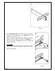
Fig. 3 3. If the Guide rails (03) have been cut, you will need to reinstall the roller stoppers on each Guide rail on both sides where it has been cut. Remove existing stopper. Mark the drilling hole with a distance of 2” from the cut off edge of the Guide rail. Drill the new hole using Ø 1/8” drill bit; then fasten the stopper with screw. 1 2” ATTENTION: Do not drill Guide rail throughout, only the first layer. See Fig. 4 for details Ø1/8” 2 Fig. 4 Rev 1.
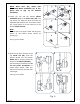
4. Fasten the bottom Guide rail (03) to the Glass profiles (01) with the Round head screws ST4.2x25 (11). See Fig. 5 for details. Fig. 5 5. Slide the Stationary glasses (05) fully into the groove of the Glass profiles (01), and then fasten it by the Glass holders (16) to the bottom Guide rail (03). 1 See Fig. 6 for details. 2 3 Fig. 6 Rev 1.
6. Slightly tap the Single side strips (09) in between the Stationary glasses (05) and the Glass profiles (01) using wooden shim or other piece of wood. The strips should be inserted from the sides that will face inside the shower. ATTENTION: Do not use the screwdriver or other metal objects; you can scratch or damage the glass and aluminum. 7. Repeat Step #4 and Step #5 to fasten the upper Guide rail (03) to the Glass profiles and secure the Stationary glasses by the Glass holders (16). See Fig.
9. Move the finished frame to the designated position on the shower base, the bathtub or the threshold (depending on your installation); push it against the walls. If your top and bottom wall opening measurements are different or if the walls are out-of-plumb, make adjustment by slightly pulling the Wall profiles (02) out of the Glass Profiles (01). Use the level to adjust the frame in the vertical position See Fig. 9 for details. Fig. 9 10.
NOTE: Glass Door (04) comes with preinstalled Wheel assemblies (17). If not, please refer to (Fig. 11) for detailed installation. 12. Fasten the top and the bottom Wheel assemblies (17) to the Glass door (04). The top wheels can adjust the door level with the adjustable bolt and lock nut. The bottom wheel has a press button to fix the wheel on to the bottom Guide rail (03). Note: The lock nut of the upper wheel and the press button of the bottom wheel should be pointing up. 1 4 2 5 3 6 See Fig.
1 14. Install the Handles (06) to the Glass doors (04). Press the anti-water strips (08) on the vertical edges of the Stationary glasses (05) and both vertical edges of the Glass doors. Press the Magnetic strips (07) on the vertical edges of both Glass doors for tight closing. See Fig. 13 for details. 2 3 Fig. 13 15. Do the final adjustments of the assembled unit in the Wall profiles (02). Drill the holes in the Glass profile (01) through predrilled holes in the Wall Profile using Ø 1/8” drill bit.
16. Apply the sealant along the profiles and guide rails; on the seams between the bottom guide rail and the profiles as well as along the shower base or threshold. See Fig. 15 for details. Caulk Fig. 15 Product Maintenance To insure long lasting life for your acrylic back walls, wipe them off after each use with a soft cloth. To clean the acrylic back walls use non-abrasive sprays or cream based cleaners. Never use abrasive cleansers, metal brushes or scrapers that could scratch or dull the surface.
WARRANTY DREAMLINE™ LIMITED WARRANTY This is Bath Authority LLC’s (“DreamLine”) exclusive written warranty effective April 2, 2012 This warranty extends only to the original owner/end-user for household use only and is not transferable to a subsequent owner. This warranty applies only to DreamLine™ products purchased from an authorized dealer and installed in United States or Canada. Proof of purchase (original sales receipt) must be provided with all warranty claims.
TEL: 866-731-8378 – 215-957-1411 FAX: 866-227-9245 – 215-893-1780 WWW.BATHAUTHORITY.COM For more information on DreamLineTM Shower Doors & Tub Doors please visit www.BathAuthority.com Rev 1.