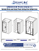
UNIDOOR PLUS (Style F) SHOWER DOOR AND INLINE PANEL INSTALLATION INSTRUCTIONS PLEASE REVIEW THIS ENTIRE MANUAL PRIOR TO INSTALLATION + STEP 1: Install Shower Door = STEP 2: Install Inline Panel STYLE F 1-866-731-2244 For more information about DreamLine® products please visit DreamLine.
©2018 DreamLine. All Rights Reserved UNIDOOR/UNIDOOR-LS/UNIDOOR LUX/UNIDOOR PLUS SINGLE SHOWER DOOR INSTALLATION INSTRUCTIONS IMPORTANT DreamLine® reserves the right to alter, modify or redesign products at any time without prior notice. For the latest up-to-date technical drawings, manuals, warranty information or additional details please refer to this model’s web page on DreamLine.
©2018 DreamLine. All Rights Reserved Style “A” (single door installation shown) with Half-Frosted Glass: NOTE: This model features the Half-Frosted glass option. The textured surface on the door glass should be installed to face outside of the shower. The door glass can be flipped for left or right-hand installation. Hinged Left installation Hinged Right installation 2 UNIDOOR Single Shower Door manual Ver 2 Rev 6.
©2018 DreamLine. All Rights Reserved Table of Contents Section Title Unidoor Styles Page # 4-7 Preparation 8 Tools 9 Required Reinforcement locations 10 Glass and Hinge hole details 11-12 Detailed Diagram of Shower Door Components and Parts List 13 Installation Instructions 14-21 Adjustable Hinge Details 17-18 Handle 19 Vinyl Seals 19-20 Product Maintenance 22 3 UNIDOOR Single Shower Door manual Ver 2 Rev 6.
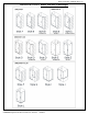
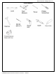
©2018 DreamLine. All Rights Reserved UNIDOOR STYLES- Models with Glass-to-Wall hinges 4 UNIDOOR Single Shower Door manual Ver 2 Rev 6.
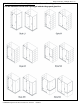
©2018 DreamLine. All Rights Reserved Models with Glass-to-Glass Hinge panels: For Glass-to-Glass Hinge Door models: Use the installation manual that is packaged with the Hinge panel glass first. 5 UNIDOOR Single Shower Door manual Ver 2 Rev 6.
©2018 DreamLine. All Rights Reserved STYLE A UNIDOOR Single shower door 23”- 30” Refer to detailed diagram on page 12 of this manual to begin the installation.
©2018 DreamLine.
©2018 DreamLine. All Rights Reserved Preparation 1. Prior to installation, examine all boxes and packages for shipping damage and compare the piece count with your packing slip. After opening all boxes and packages read this introduction carefully. Check that all of the necessary parts are included in the package(s) by checking off the components on the “Detailed Diagram of Shower Door Components”.
©2018 DreamLine. All Rights Reserved Tools Required 9 UNIDOOR Single Shower Door manual Ver 2 Rev 6.
©2018 DreamLine. All Rights Reserved 10 UNIDOOR Single Shower Door manual Ver 2 Rev 6.
©2018 DreamLine. All Rights Reserved 11 UNIDOOR Single Shower Door manual Ver 2 Rev 6.
©2018 DreamLine. All Rights Reserved 12 UNIDOOR Single Shower Door manual Ver 2 Rev 6.
©2018 DreamLine.
©2018 DreamLine. All Rights Reserved Single Shower Door Assembly and Installation NOTE: The following shower door installation instructions should be used as a general guide and prerequisite to the installation of the UNIDOOR, UNIDOOR-LS, UNIDOOR LUX and UNIDOOR PLUS models. Before you begin the installation, please check your finished opening size. Specific size information can be found on DreamLine.
©2018 DreamLine. All Rights Reserved 2. The Door Glass (01) ships with four 5/8” shims attached to the top (2pcs) and bottom (2pcs). Determine the swing of your door and only remove the shims from the top of the door glass, leaving the bottom shims in place. Set the Door Glass (01) onto the threshold at the desired location and check for level.
©2018 DreamLine. All Rights Reserved 1 TIP: The PVC hinge spacer can also be used as a template to assist with marking the hinge mounting holes. 2 *Only use the PVC hinge spacer to correct for minor out-of-plumb wall conditions. 3 Fig. 4 ATTENTION: As viewed from inside the shower, the hinge plate is very close to the drilled holes in the wall and might get scratched while installing the long screws. Be careful not to scratch the hinge surfaces during installation. (OPTIONAL) 5.
©2018 DreamLine. All Rights Reserved Setting the Adjustable Hinges The Adjustable hinges are pre-set to overclose to 85º and are adjustable up to 90º after the door is installed. Once the door glass is installed, simply loosen the Allen set screws and position the door to the desired closed position. While holding the door in the new closed position, retighten the Allen screws and your door will now self-center to the chosen closed position. 5a.
©2018 DreamLine. All Rights Reserved 5b. The hinges are factory set to 85 degrees. You can change this angle by using the adjustment screws on the hinge plate. (Fig 5b) outside inside Fig 5b 5c. Use the supplied Allen Key to loosen the adjustment screws on the inside hinge plate, adjust the door to the desired angle (90 degrees for example) then retighten the adjustment screws (Fig 5c). Be sure that you create a tight seal with the supplied strike vinyl when the door is in the closed position.
©2018 DreamLine. All Rights Reserved 6. Mount the Handle (02) to the Door Glass (01). (Fig 6) Fig. 6 7. Measure the bottom of the Door Glass (01) from end to end to determine the actual width of the door. Cut the Bottom anti-water strip (07) to the size of your measurement and notch approximately 3/8” off the inner side of the Bottom anti-water strip as shown. Press the Bottom Anti-water strip (07) tightly onto the bottom edge of the Door Glass (01).
©2018 DreamLine. All Rights Reserved 1 2 7/8" Into the hinge Into the hinge 3 4 7/8" 7/8" 8. Take three measurements: from the top edge of the Door Glass (01) to the upper body of the top Hinge (05) (+) 7/8” from the lower body of the upper Hinge to the upper body of the bottom Hinge (+) 1-3/4” from the lower body of the bottom Hinge to top of the installed Bottom anti-water strip (07) (+) 1-7/8” Cut the Side strip (06) according to the measurements.
©2018 DreamLine. All Rights Reserved Fig. 10 If the model includes additional panel glass, refer to the manual that is packaged with the panel glass to continue with the installation. 21 UNIDOOR Single Shower Door manual Ver 2 Rev 6.
©2018 DreamLine. All Rights Reserved Product Maintenance BASES and BACKWALLS: To ensure long-lasting life for your acrylic back walls: wipe them off after each use with a soft cloth. To clean the acrylic back walls use non-abrasive sprays or cream based cleaners. Avoid the use of aerosol spray cleaners. Never use abrasive cleansers, metal brushes or scrapers that could scratch or dull the surface.
©2018 DreamLine. All Rights Reserved TEL: 866-731-2244 FAX: 866-857-3638 DREAMLINE.COM For more information on DreamLine® Shower Doors and Enclosures please visit DreamLine.com 23 UNIDOOR Single Shower Door manual Ver 2 Rev 6.
Install the door first INLINE PANEL ® (STYLE F) d INLINE PANEL GLASS ILNSTALLATION ine rveINSTRUCTIONS e s m e PLEASE REVIEW THIS ENTIRE MANUAL PRIOR TO INSTALLATION a R e Dr ghts © Ri All d e e in erv L s m e a R e r s D ght © Ri All ® *with L-Bar™ support bracket right-hand inline panel installation shown *L-Bar™ only included with ELEGANCE PLUS models with nominal panel glass sizes 22”, 22-1/2”, 30”, 30-1/2”& 34” IMPORTANT! DreamLine® reserves the right to alter, modify or redesign products at an
This model is treated with DreamLine’s exclusive ClearMaxTM Glass technology. This is a specially formulated coating that prevents the build up of soap and water spots. Install the surface with the ClearMaxTM label towards the inside of the shower. Please note that depending on the model, the glass may be coated on either one or both surfaces. For best results, squeegee the glass after each use and dry with a ® soft cloth.
Section Title ClearMax™ Coating Information Warnings and General Preparaton Model Specific Preparation ® Tools Detailed Diagram of Inline Panel Glass Components Parts List Installation Steps 180º Strike Vinyl Installation Reversible L-Bar™ Installation (*for ELEGANCE PLUS model only) Product Maintenance Reversible L-Bar™ Feature Troubleshooting Factory Parts Information Product SKUs d e e n v i r L e s m e a R e Dr ghts © Ri All d e e n v Symbol Legendi r L e s m e a R e Dr ghts © Ri All Page # — 2 3 4 5
d e e n v i r L e s m e a R e r s D ght © Ri All WARNING DISCLOSURE STATEMENT IMPORTANT • • • DreamLine® reserves the right to alter, modify or redesign products any time without prior notice for product improvement and customer experience. Please refer to the model’s web page on DreamLine.com for the latest technical drawings, installation manuals, warranty information or additional product details.
©2020 DreamLine® All Rights Reserved Model Specific Preparation ! REQUIRED: minimum threshold 1/2” Out-of-Plumb Adjustment with the Inline Panel; Verify threshold and walls with a level Threshold must be level ±0.0 d e e n v i r L e s m e a R e Dr ghts © Ri All ® ±0.0 ! Tile TIP Acrylic 5/8” minimum flat threshold right-hand orientation shown Tub Contact the manufacturer of the base, tub or threshold material with any questions regarding the drilling of holes into their product.
©2020 DreamLine® All Rights Reserved Tools Tape Measure Level Drill Bit Ø1/8" (3mm) Drill Bit Ø3/16" (4mm) Metal File TIP #2 Phillips Screwdriver Pencil 100 % Silicone d e e n v i r L e s m e a R e Dr ghts © Ri All Drill Bit Ø5/16" (8mm) Safety Glasses #2 Phillips Driver Bit ® Soft Head Hammer Work Gloves Hacksaw Razor Knife OR Power Drill Mitre Saw Professional-grade Glass Suction Cup (optional but recommended) Measure the finished opening before proceeding with the installation to b
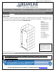
INLINE PANEL (STYLE F) Glass Installation Manual Ver 2 Rev 1 012020 Detailed Diagram of Inline Panel Glass Components ® d e e in erv L s m e a R e r s t D gh 11 © Ri All 09 19 23 d e 29 e in erv L s m e a R e r s t D gh © Ri l l A 13 09 ® The glass surface with the ClearMax™ label must be installed facing the inside of the shower 23 5 right-hand panel installation shown © 2019 DreamLine® All Rights Reserved
©2020 DreamLine® All Rights Reserved Parts List 09 11 13 d e e n v i r L e x1 x1 s m e a R e Dr ghts © R23i 28 l Al ® Vertical U-Channel 19 180˚ Strike Vinyl Inline Panel Glass x1 29 ST4.2×40mm Countersunk Screw x18 Wall Anchor Ø5/16” (8mm) x18 PVC Glass Spacer 0.
INLINE PANEL (STYLE F) Glass Installation Manual Ver 2 Rev 1 012020 The Unidoor Plus, Unidoor-X or Elegance Plus Shower Door must be installed prior to proceeding with the following Inline Panel Glass installation instructions.
INLINE PANEL (STYLE F) Glass Installation Manual Ver 2 Rev 1 012020 Installation Steps 1 d e e in erv L s m e a R e r s t D gh © Ri All 1 ® 2 insid e outs ide TIP To assist with aligning the Inline Panel Glass (#11) with the pre-installed Door Glass, hold the door glass parallel with the outside of the threshold and mark a reference line on the threshold.
INLINE PANEL (STYLE F) Glass Installation Manual Ver 2 Rev 1 012020 2 d e e in erv L s m e a R e r Glass s t D gWidth © Ri h (W) All ® W Glass Height (H) H d e e in erv L s m e a R e r s t D gh © Ri l l A ® Fig 2 Parts Needed 11 x1 Tools Needed 9 © 2019 DreamLine® All Rights Reserved
INLINE PANEL (STYLE F) Glass Installation Manual Ver 2 Rev 1 012020 3 Cut the Bottom U-Channel to: ® Glass Width (W) + 3/16” = (L)** (see exception below) Fig 3 (L) TIP d e e in erv L s m e a R e r s t D gh © Ri All OR (L) Plumb line Use a metal file to deburr the cut end ! **EXCEPTION: If the wall is out-of-plumb at the bottom, measure that dimension as (A) and add (A) to the finished cut length of the U-channel (+1/2” max): d e e in erv L s m e a R e r s t D gh © A Ri l l A ® Out-of-plumb at
INLINE PANEL (STYLE F) Glass Installation Manual Ver 2 Rev 1 012020 4 d e e in erv L s m e a R71” (1803.
INLINE PANEL (STYLE F) Glass Installation Manual Ver 2 Rev 1 012020 5 d e e in erv L s m e a R e r s t D gh © Ri All Fig 5b ® Fig 5a 2” (50.8mm) d e e in erv L s m e a R e r s t D gh © Ri l l A ® ! Cut several 2” - 3” pieces of the PVC Glass Spacer 0.5mm (#28).
INLINE PANEL (STYLE F) Glass Installation Manual Ver 2 Rev 1 012020 6 d e e in erv L s m e a R e r s t D gh © Ri All ® d e e in erv L s m e a R e r s t D gh © Ri l l A ® Fig 6a NOTE The 180˚ Strike Vinyl (#19) will extend above the panel glass for now, but will be notched to fit around the bottom u-channel. See step#14.
INLINE PANEL (STYLE F) Glass Installation Manual Ver 2 Rev 1 012020 7 1/2” MAX d e e in erv L s 2 1am e R e r s t D gh © Ri All ® inline pane l doo door 3 panel r 1/16” - 1/8” 4 5 d e e in erv L s m e a R e r s t D gh © Ri l l A ® NOTE Fig 7 NOTE The top of the Inline Panel Glass must be flush with the top of the Door Glass. (Fig 7.3) The Vertical U-Channel (#09) will allow for up to 1/2” of out-of-plumb adjustment.
INLINE PANEL (STYLE F) Glass Installation Manual Ver 2 Rev 1 012020 8 d e e in erv L s m Fige 8b a R e r s t D gh © Ri All ® Fig 8c d e e in erv Fig 8a L s m e a R e r s t D gh © Ri l l A ® NOTE Remove the PVC Glass Spacers 0.5mm (#28) from the Bottom U-Channel (#29). (Fig 8c) These must be reinstalled in step #12.
INLINE PANEL (STYLE F) Glass Installation Manual Ver 2 Rev 1 012020 9 NOTE Fig 9 NOTE The surfaces need to be clean and free of debris before applying silicone. d e e in erv L s m e 1 2 a R e r s t D gh © Ri All 3 1 3 ® 2 d e e in erv L s m e a R e r s t D gh © Ri l l A ◾For installation into an Acrylic Threshold: drill an Ø1/8”(3mm) hole and use the ST4.2 x 40mm Countersunk Screw (#23) OR ◾For installation into a Tile Threshold: drill a Ø3/16”(4.
INLINE PANEL (STYLE F) Glass Installation Manual Ver 2 Rev 1 012020 10 d e e in erv L s m e a R e r s t D gh © Ri All ® 1 ® ! 2 e r n i L e s m e Fig 10 a R e r s t D gh © Ri l l A d e v Parts Needed 23 x4 Tools Needed To prevent damage to the glass, be sure that the screws are fully countersunk and that the screw heads do not stick up above the surface of the u-channel 17 © 2019 DreamLine® All Rights Reserved
d e e in erv L s m e a R e r s t D gh © Ri 1 All 2 ® ® Fig 11 e r n i L e s m e a sR e r D ght © Ri l l A d e v 3 ip olt to INLINE PANEL (STYLE F) Glass Installation Manual Ver 2 Rev 1 012020 11 Parts Needed 23 x4 Tools Needed 18 © 2019 DreamLine® All Rights Reserved
INLINE PANEL (STYLE F) Glass Installation Manual Ver 2 Rev 1 012020 12 1 d e e in erv L s m e a R e r s t D gh © Ri All ® 2 d e e in erv L s m e a R e r s t D gh © Ri l l A Fig 12 NOTE 3 ® After applying silicone into the bottom U-Channel install several 2” - 3” pieces of the PVC Glass Spacer 0.5mm (#28) into the Bottom U-Channel (#29) to protect the bottom edge of the glass. (Fig 12.
INLINE PANEL (STYLE F) Glass Installation Manual Ver 2 Rev 1 012020 13 2d e e in erv L s m e a R e r s t D gh © Ri ll A 1 1 ® 1 2 2 d e e in erv L s m e a Fig 13 e R r s t D gh © Ri l l A ® Tools Needed 20 © 2019 DreamLine® All Rights Reserved
INLINE PANEL (STYLE F) Glass Installation Manual Ver 2 Rev 1 012020 180° Strike Vinyl Installation 14 d e e in erv L s m e a 2 R e r s t D gh © Ri All ® 1 3 inside inline panel 1” 4 door panel d e e 1/16” 1/8” n v i r L e s m e a sR e Fig 14 r D ght © Ri l l A ® Parts Needed 19 x1 Tools Needed 21 © 2019 DreamLine® All Rights Reserved
INLINE PANEL (STYLE F) Glass Installation Manual Ver 2 Rev 1 012020 15 The surfaces need to be clean and free of debris before applying silicone. NOTE d e e in erv L s m e a R e r s t D gh © Ri All ® 24 Hours NOTE If the model does not include an L-Bar™ Support Bracket, this completes the Inline Panel installation.
INLINE PANEL (STYLE F) Glass Installation Manual Ver 2 Rev 1 012020 Reversible L-Bar™ Installation 16 (L-Bar™ for ELEGANCE PLUS model only) d e e in erv L s m e a R e r s t D gh © Ri All ® 30.5 30.2 30.6 30.9 30.10 30.8 30.1 30.7 30.11 30.3 30.12 30.4 Right-handed orientation shown* NOTE NOTE Item Item Description Quantity 30.1 30.2 30.3 30.4 30.5 30.6 30.7 30.8 30.9 30.10 30.11 30.
INLINE PANEL (STYLE F) Glass Installation Manual Ver 2 Rev 1 012020 17 3 d e e in erv L s m e a R e r s t D gh © Ri All 1 ® 2* 5 6 7 d e e in erv L m Res TIP rea D ghts © Ri l l A Fig 17 4 ® right-handed installation shown *see NOTE *Leave the L-Bar™ decorative cover attached when marking the L-Bar™ position on the wall to allow space (1/16”-1/8”) to re-attach the cover plate after installation. NOTE 24 *The 0.5mm PVC Spacer (#30.4) for the L-Bar™ Glass Holder (#30.
INLINE PANEL (STYLE F) Glass Installation Manual Ver 2 Rev 1 012020 18 1 2 ® e in3* d e rv L e s m e a sR e r D ght © Ri All Max 3/16” (4mm) 4* Max 3/16” (4mm) Fig 18 right-handed installation shown d e e in erv L s m e a R e r s t D gh © Ri l l A ® NOTE * To adjust the angle of the L-Bar™: 25 Loosen the M5 x 14.5 screws, rotate the appropriate set screw (See Fig 18.3 and 18.4) to adjust the angle of the L-Bar™ (up to 3/16” (4mm)) in the desired direction. Hand tighten the M5 x 14.
INLINE PANEL (STYLE F) Glass Installation Manual Ver 2 Rev 1 012020 19 d e e n erv i L 2 s m e a R e r s t D gh © Ri All ® 1 0 - 1/16” (2mm) 3 Fig 19 right-handed installation shown d e e in erv L s m e a R e r s t D gh © Ri l l A ® Tools Needed 26 © 2019 DreamLine® All Rights Reserved
©2020 DreamLine® All Rights Reserved Product Maintenance BASES and BACKWALLS: To ensure long lasting life for your acrylic back walls: wipe them off after each use with a soft cloth. To clean the acrylic back walls use non-abrasive sprays or cream based cleaners. Avoid the use of aerosol spray cleaners. Never use abrasive cleansers, metal brushes or scrapers that could permanently scratch or dull the surface.
INLINE PANEL (STYLE F) Glass Installation Manual Ver 2 Rev 1 012020 Reversible L-Bar™ Feature: Glass Holder (for ELEGANCE PLUS®model only) left-handed orientation Step 1 d e e in erv L s m e a R e r s t D gh © Ri l l A 1 2 3 4 6 5 d e e in erv L s m e a R e r s t D gh © Ri l l A ® Tools Needed 28 left-to-right handed orientation shown © 2019 DreamLine® All Rights Reserved
INLINE PANEL (STYLE F) Glass Installation Manual Ver 2 Rev 1 012020 Reversible L-Bar™ Feature: Wall Bracket 1 5 2 6 9 d e rv ® in3 e L e s m e a sR e r D ght © Ri All 7 Step 2 4 8 ® n10e i L e s m e a sR e r D ght © Ri l l A d e rv right-handed orientation Tools Needed 29 left-to-right handed orientation shown © 2019 DreamLine® All Rights Reserved
Problem/Symptom Suggested Solution •Check all shipping/packaging material for missing parts/components. •If not found, contact DreamLine Customer Support [1-866-731-2244] to order factory part replacement. Missing Parts •Inspect the 180º Degree Strike Vinyl (#19) and ensure the orientation of the Door Glass does not close vinyl is correct.
INLINE PANEL (STYLE F) Glass Installation Manual Ver 2 Rev 1 012020 Factory Parts Information d e e in erv L s m e a R e r s t D gh © Ri All INLINE PANEL [STYLE F] - HARDWARE ITEM # ® FACTORY PART NUMBER FACTORY PARTS INFORMATION ITEM DESCRIPTION 09 04154011-1930 / 04154041-1930 / 04154061-1930 / 04154091-1930 U-Channel 1" Aluminum for 10mm (3/8in.
©2020 DreamLine® All Rights Reserved Product SKUs d e e n v i r L e s m e a R e Dr ghts © Ri All ® Elegance Plus w/inline panel SHDR-443060-## SHDR-443465-## SHDR-444014-## SHDR-444622-## SHDR-4452225-## SHDR-4458305-## Unidoor Plus Style F SHDR-242907210-## SHDR-243007210 SHDR-243107210 SHDR-243207210 SHDR-243307210 SHDR-243407210 SHDR-243507210 SHDR-243607210 SHDR-242957210 SHDR-243057210 SHDR-243157210 SHDR-243257210 SHDR-243357210 SHDR-243457210 SHDR-243557210 SHDR-243657210 SHDR-243707210 SHDR-2438
©2020 DreamLine® All Rights Reserved Product SKUs d e e n v i r L e s m e a R e Dr ghts © Ri All ® Unidoor-X Style M1 D12306572-## D1230672 D12314572 D1231472 D12322572 D1232272 D12330572 D1233072 D12406572 D1240672 D12414572 D1241472 D12422572 D1242272 D12430572 D1243072 D12506572 D1250672 D12514572 D1251472 D12522572 D1252272 D12530572 D1253072 D12606572 D1260672 D12614572 D1261472 D12622572 D1262272 D12630572 D1263072 D12706572 D1270672 D12714572 D1271472 D12722572 D1272272 D12730572 D1273072 D128065
d e e n v i r L e s m e a R e Dr ghts © Ri All ® d e e n v i r L e s m e a R e Dr ghts © Ri All ® TEL: 866-731-2244 FAX: 866-857-3638 DREAMLINE.COM For more information on DreamLine® Shower Doors and Enclosures please visit DreamLine.