SLIMLINE SHOWER BASE SHOWER BASE DIMENSIONS AND INSTALLATION INSTRUCTIONS IMPORTANT DreamLine® reserves the right to alter, modify or redesign products at any time without prior notice. For the latest up-to-date technical drawings, manuals or additional details please refer to your model’s web page on DreamLine.com Please read these instructions carefully before installing.
Preparation 1. Prior to installation, examine all boxes and packages for shipping damage and compare the piece count with your packing slip. After opening all boxes and packages, read this introduction carefully. Check that all of the needed parts are included in the package by checking off the components on the “Detailed Diagram of Shower Door Components”.
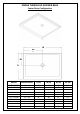
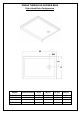
SINGLE THRESHOLD SHOWER BASE Center Drain Configuration W W1 11 D1 D MODEL SPECIFICATION D (in) W (in) D1 (in) W1 (in) DLT-1132320 DLT-1136360 32"× 32" 36"× 36" 32" 36" 32" 36" 15" 15" 16" 18" DLT-1134420 34” x 42” 34” 42” 15” 21” DLT-1132480 DLT-1134480 DLT-1136480 DLT-1130600 DLT-1132600 DLT-1134600 DLT-1136600 32"× 48" 34” x 48” 36"× 48" 30"× 60" 32"× 60" 34"× 60" 36"× 60" 32” 34” 36" 30" 32" 34" 36" 48” 48” 48" 60" 60" 60" 60" 15” 15” 15" 15" 15" 15" 15" 24” 24” 24" 30" 30" 30"
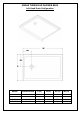
SINGLE THRESHOLD SHOWER BASE Left-Hand Drain Configuration W W1 D1 D MODEL SPECIFICATION D (in) W (in) D1 (in) W1 (in) DLT-1130601 DLT-1132601 DLT-1134601 DLT-1136601 30"×60" 32"×60" 34"×60" 36"×60" 30" 32" 34" 36" 60" 60" 60" 60" 15" 15" 17" 18" 12" 12" 12" 12" “SLIMLINE SHOWER BASE” Ver.5 Rev.
SINGLE THRESHOLD SHOWER BASE Right-Hand Drain Configuration W W1 D1 D MODEL SPECIFICATION D (in) W (in) D1 (in) W1 (in) DLT-1130602 DLT-1132602 DLT-1134602 DLT-1136602 30"×60" 32"×60" 34"×60" 36"×60" 30" 32" 34" 36" 60" 60" 60" 60" 15" 15" 17" 18" 12" 12" 12" 12" “SLIMLINE SHOWER BASE” Ver.5 Rev.
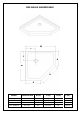
NEO ANGLE SHOWER BASE W C C A W B A MODEL SPECIFICATION W (in) A (in) B (in) C (in) DLT-2036360 DLT-2038380 DLT-2040400 DLT-2042420 36"×36" 38"×38" 40"×40" 42"×42" 36" 38" 40" 42" 18 5/16" 20 5/16" 22 5/16" 24 5/16" 25" 25" 25" 25" 12" 12" 14 3/8" 14 3/8" “SLIMLINE SHOWER BASE” Ver.5 Rev.
QUARTER ROUND SHOWER BASE W C C W R MODEL SPECIFICATION W (in) C (in) R (in) DLT-7033330 DLT-7036360 DLT-7038380 33"×33" 36"×36" 38"×38" 33" 36" 38" 12" 12" 12" 21 5/8" 21 5/8" 21 5/8" “SLIMLINE SHOWER BASE” Ver.5 Rev.
DOUBLE THRESHOLD SHOWER BASE Corner Drain Configuration W C C W MODEL SPECIFICATION W (in) C (in) DLT-1032320 DLT-1036360 32"×32" 36"×36" 32" 36" 12" 12" “SLIMLINE SHOWER BASE” Ver.5 Rev.
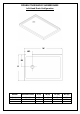
DOUBLE THRESHOLD SHOWER BASE Left-Hand Drain Configuration W W1 D1 D MODEL SPECIFICATION D (in) W (in) D1 (in) W1 (in) DLT-1034481 DLT-1036481 DLT-1036601 34"×48" 36"×48" 36"×60" 34" 36" 36" 48" 48" 60" 17" 18" 18" 12" 12" 12" “SLIMLINE SHOWER BASE” Ver.5 Rev.
DOUBLE THRESHOLD SHOWER BASE Right-Hand Drain Configuration W W1 D1 D MODEL SPECIFICATION D (in) W (in) D1 (in) W1 (in) DLT-1034482 DLT-1036482 DLT-1036602 34"×48" 36"×48" 36"×60" 34" 36" 36" 48" 48" 60" 17" 18" 18" 12" 12" 12" “SLIMLINE SHOWER BASE” Ver.5 Rev.
Shower Base Cross Section Diagram Shower Base Cement board Finished Wall (2"×4") Stud Mortar Drain “SLIMLINE SHOWER BASE” Ver.5 Rev.
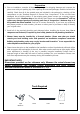
Shower Base Installation - Preparation 1. Ensure that the floor and the studs are at right angles. Provide a 5”×5” opening in the subfloor for the drain. The 2” PVC waste pipe should extend above the surface of the sub-floor according to the drain installation instructions and the height of the Shower base. Refer to the product drawings and tables in these installation instructions for the drain location. 90° 90° 90° See Fig. 1 and Fig. 2 for details.
2. Install the shower drain (NOT INCLUDED) according to the drain installation manual (supplied with the drain). See Fig. 3 for example Fig. 3 3. Place the tray into the designated position so that the Drain Body drops around the Drain Pipe and butt the Shower Base up against the studs. See Fig. 4 for details. Lower the base over the drain pipe and set it into place against the studs. Fig. 4 “SLIMLINE SHOWER BASE” Ver.5 Rev.
4. Level the tray and place marks on the studs above the upper edge of the tile flange. See Fig. 5 for details. Level base in two directions Fig. 5 5. Mix the bedding material (Mortar, cement-sand mix, etc.) Concrete or plaster is not recommended. Apply enough bedding material to support the entire bottom of the shower base. This will add additional stability and prevent the base from shifting position. See Fig. 6 for details. Mortar Fig. 6 “SLIMLINE SHOWER BASE” Ver.5 Rev.
6. After the bedding material has been poured and before it sets, place the shower base into the position with the drain assembly sliding over the PVC waste pipe. It will be necessary to push the shower base until the top of the tile flange aligns with the marks drawn on the studs and the front edge is contacting the rough floor along the entire length of the shower base. Ensure that the base is level in all directions.
Fig. 9 Product Maintenance BASES and BACKWALLS: To ensure a long life for your acrylic back walls: wipe them off after each use with a soft cloth. To clean the acrylic back walls use non-abrasive sprays or cream based cleaners. Never use abrasive cleansers, metal brushes or scrapers that could scratch or dull the surface. GLASS: To ensure long lasting life for your glass shower products: wipe them off after each use with a soft cloth.
TEL: 866-731-2244 FAX: 866-857-3638 DREAMLINE.COM For more information on DreamLine® Shower Doors and Enclosures please visit DreamLine.