PRISM PLUS with Buttress Return Panel SHOWER ENCLOSURE INSTALLATION INSTRUCTIONS d e rve n i L e s m e a R e Dr ghts © Ri All IMPORTANT DreamLine® reserves the right to alter, modify or redesign products at any time without prior notice for the purpose of product improvement and customer experience. Please refer to the model’s web page on DreamLine.com for the latest technical drawings, installation manuals, warranty information or additional product details.
d e e in erv L s m e a R e r s t D gh © Ri l l A This model is treated with DreamLine’s exclusive ClearMaxTM Glass technology. This is a specially formulated coating that prevents the build up of soap and water spots. Install the surface with the ClearMaxTM label towards the inside of the shower. Please note that depending on the model, the glass may be coated on either one or both surfaces.
The hinge panel glass must be properly installed and secured to support the weight of the door glass. Failure to follow these steps may result in the hinge panel glass pulling out of the U-Channel.
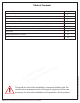
Table of Contents Section title Enclosure Diagram Page # 2 Tools Detailed Diagram of Shower Enclosure Components Parts List Installation Steps L-Bar™ Installation Vinyl Seals d e v e r n i L e s m e a sR e r D ght © Ri l l A 3 4 5 6 7-20 10-11 19 Hinge Adjustment Procedure 21 Product Maintenance 22 d e e in serv L m e a R e Dr ghts © Ri l l A ! This product should be installed by someone familiar with the construction requirements for this type of project and the care necessary for the safe inst
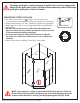
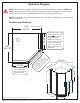
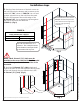
Enclosure Diagram ! NOTE: This enclosure must be installed at the model size dimensions shown in Table A on page 7. Be sure that the correct size shower enclosure has been ordered to fit the finished dimensions of the base or threshold that the enclosure will be installed upon. NOTE: The thickness of the finished wall treatment will affect the alignment of the enclosure upon the threshold.
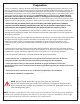
Preparation 1. Prior to installation, examine all boxes and packages for shipping damage and compare the piece count with your packing slip. After opening all boxes and packages read this introduction carefully. Check that all of the needed parts are included in the package by checking off the components on the “Detailed Diagram of Shower Door Components”.
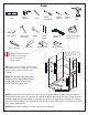
Tools Level 13/16” shims 100% Silicone* ! Tape Measure Pencil Drill bit (Ø5/16") Phillips Screwdriver d e e in serv L m e a R e Dr ghts © Ri l l A Soft-Head Hammer Razor Knife Mallet Wood Block Work Gloves Carpenter’s Square Drill bit (Ø1/8") Power Drill Professional-grade Glass suction cup Safety Glasses *The Buttress return panel glass location will be aligned after the door glass is installed. *Quick-drying/fast-curing silicone recommended for the installation of hinge panels.
Detailed Diagram of Shower Enclosure components 9 12 6 4 11 d e e in serv L m Re a e Dr ghts © Ri All 1 3 17 16 14 10 2 d e e in serv L m Re a e 7 8s 15 Dr t © Righ All 5 ©2018 DreamLine.
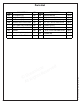
Parts List DESCRIPTION U-Channel (72”) Hinge Panel Glass QTY 1pc 1pc ITEM # 03 04 U-Channel (34”) 1pc 1pc 12 13 130º Glass-to-Glass Adj Hinge ST 4.2 x 40 Pan head screw QTY 2pcs 1pc 2pcs 6pcs 05 135° Strike Vinyl w/VHB tape 1pc 14 Anchor (5/16”) 6pcs 06 Door Glass 1pc 15 Hinge-side vinyl 1pc 07 Handle 1pc 16 ST 4.
Installation steps 1. Starting from the bottom of the back corner on the wall opposite the buttress wall, measure to the model size “W1” shown in TABLE A. Use a 4’ level to draw a plumb line up the wall from that mark. This line will represent the outside edge of the U-Channel (#1). Use a carpenter’s square against the wall to also mark the threshold.
3. Drill the holes into the wall using a Ø 5/16”(8mm) drill bit and insert the Anchors (#14). Run a bead of waterproof silicone along the back of the U-Channel (72”) (#01). Fasten the U-Channel (72”) (#01) to the wall using the ST4.2×40 Pan Head screws (#13). (Fig 3) 1 2 Ø8(5/16") 3 4 d e e in serv L m e a R e Dr ghts © Ri l l Fig 3 A 4. Apply silicone into the installed U-Channel (72”) (#01). (Fig 4) ! d e e in serv L m e a R e Dr ghts © Ri l l A ©2018 DreamLine.
5. Set the Hinge Panel Glass (#02) onto the threshold and into the installed U-Channel (72”) (#01). Check for level and plumb. (Fig 5a/Fig 5b) ! NOTE: Use caution not to damage the glass when setting it into place. d e e in serv L m e a R e Dr ghts © Ri l l A This model has 1/4” of adjustment for out-of-plumb wall conditions within the U-channels. Do not exceed this tolerance. hinge panel glass u-channel Fig 5a d e e in serv L m e a R e Dr ghts © Ri l l A ©2018 DreamLine.
Installation steps for L-Bar™ L-Bar™ Assembly Parts List (left hand bracket shown) 9.5 d e e in erv L s m e a R e r s D ght © Ri All 9.9 9.4 9.3 9.6 9.2 9.7 9.1 9.8 Item# DESCRIPTION 9.1 PVC spacer 9.2 Qty Item# DESCRIPTION Qty 1 pc 9.6 Wall plate 1 pc Rubber tip set screw 2 pcs 9.7 Truss Head Screw ST 4.2 x 40 2 pcs 9.3 L-Bar™ (left hand shown) 1 pc 9.8 Flat head Screw M5 x 14 2 pcs 9.4 Decorative cover 1 pc 9.9 Wall Plate adjustment set screw 2 pcs 9.
6. Position the Left-hand L-Bar™ (#9) onto the Hinge Panel Glass (#02) as shown and mark its position on the wall. Remove the Wall Plate (#9.6) from the Left-hand L-Bar™ (#9). Hold the Wall Plate (#9.6) to the marks on the wall. Hold the Wall Plate (#9.6) level and mark the holes for drilling through the wider, untapped holes. (Fig 8.2) Drill two Ø5/16”(8mm) holes and insert the Ø5/16” Wall anchors (#9.5).
8. Measure the distance on the threshold between the Hinge Panel Glass (#02) and the buttress wall. Adjust the Hinge Panel Glass (#02) so it is parallel to the outside edge of the threshold. Measure the area where the door glass will be installed. This distance needs to be 23-13/16”as measured from the inside edge of the Hinge Panel Glass (#02) to the inside edge of the Buttress Return Panel Glass (#04) and the buttress wall. Mark the position of the door glass on the threshold as shown.
NOTE: It is advisable to allow the silicone holding the ! Hinge Panel Glass (#02) in the U-Channel (72”) (#01) to cure before hanging the Door Glass (#06). ! TIP: Use a 13/16” shim beneath the door glass to help align the Door Glass (#06) with the hinges. This will protect the threshold and the bottom of the door glass from damage and allow proper spacing for the Sweep Vinyl (#08).
! NOTE: Protect the edge of the door glass to prevent contact with the buttress wall during installation. 10. Carefully bring the Door Glass (#06) into the shower between the Hinge Panel Glass (#02) and the buttress wall. USE CAUTION: Do not to let the glass contact the wall or threshold. Level up the Door Glass (#06) next to the Hinge Panel Glass (#02) and fasten the 130º Glass-to-Glass Adj Hinge (#12) onto the Door Glass (#06).
11. Attach the U-Channel (34”) (#03) to the Buttress Return Panel Glass (#04) and dry-fit the glass onto the buttress wall. and align with the Door Glass (#06). Adjust for level and plumb. If necessary, the Buttress Return Panel Glass (#04) can be pulled out of the U-channel 1/4” max. to align flush with the end of the buttress wall.
13. Add silicone to the inside of the installed U-Channel (34”) (#03). Slide the Buttress Return Panel Glass (#04) back into the U-Channel (34”) (#03) and adjust the glass for level and plumb using the lines drawn in the previous step for reference. (Fig 13) ! 1 NOTE: Use caution not to damage the glass when setting it into place. d e e in serv L m Re a e Dr ghts © Ri All 2 outside outside Fig 13 14.
15. Remove the paper backing from the 135° Strike Vinyl w/VHB Tape (#05) and press it firmly onto the vertical edge of the Buttress Return Panel Glass (#04) and the buttress wall along the plumb line drawn earlier. (Fig 15) 1 2 d e v ! e r n i L e s m e a R e Dr ghts © Ri Fig 15 l Al Buttress Return Panel Glass 3 For best adhesion, allow the adhesive to set up for 24 hours prior to normal use. Buttress wall 16. Verify alignment of the door glass.
17. Press the Sweep Vinyl (#08) firmly onto the bottom edge of the Door Glass (#06) and close the door. From inside the shower, mark the inner aspect of the sweep where it overlaps the strike vinyl. Cut off approximately 3/8” and remove only the inner aspect of the Sweep Vinyl (#08) (See Fig 17.2) to allow the door to close and seal evenly against the strike vinyl, without leaving any gaps. (Fig 17) 1 2 4 3 d e e in serv L m Re a e Dr ghts © Ri Fig 17 All Inside 18.
19. Trim and notch the Hinge-side vinyl (#15) around the hinges to provide maximum water proofing: • From the top edge of the Door Glass (#06) to the top edge of the inner part of the Hinge (#12); (See Fig 19.3) • Repeat this process between the top and bottom hinges d e e in serv L m Re a e Dr ghts © Ri 2 3 l Al • Measure up from the surface of the shower base to the bottom of the inner part of the bottom hinge. Cut the Hinge-side vinyl (#15) according to these measurements.
20. Apply a good quality mildew-resistant silicone along the interior perimeter where the stationary glass panels meet the walls and the shower base or buttress wall. (Fig 20) NOTE: The surfaces need to be clean and free of debris before applying silicone. ! d e e in serv L m Re a e Dr ghts © Ri All Allow 24 hours for the silicone to cure before using the shower. 24 Hours PRISM PLUS with Buttress Shower enclosure manual Ver 1 10/2018 ©2018 DreamLine.
HG-PRS30A Adjustable Hinge Manual d e e n v i ser L m e a R e Dr ghts © Ri All Installation & Adjustment 2. The hinges are set to over- 1. Make sure the door glass is plumb and the edge of the hinge is installed flush with the glass edge. Tighten the faceplate screws. (Figure 1) close at 130°degrees. You can change this angle by using the adjustment screws on the hinge plate. (Figure 2) 3.
Product Maintenance BASES and BACKWALLS: To ensure long lasting life for your acrylic back walls: wipe them off after each use with a soft cloth. To clean the acrylic back walls use non-abrasive sprays or cream based cleaners. Avoid the use of aerosol spray cleaners. Never use abrasive cleansers, metal brushes or scrapers that could scratch or dull the surface.
d e e in serv L m e a R e Dr ghts © Ri All TEL: 866-731-2244 FAX: 866-857-3638 DREAMLINE.COM For more information on DreamLine® Shower Doors and Enclosures please visit DreamLine.com PRISM PLUS with Buttress Shower enclosure manual Ver 1 10/2018 ©2018 DreamLine.