SHCM-3300 SHOWER PANEL SHOWER PANEL INSTALLATION INSTRUCTIONS IMPORTANT DreamLine® reserves the right to alter, modify or redesign products at any time without prior notice. For the latest up-to-date technical drawings, manuals, warranty information or additional details please refer to your model’s web page on DreamLine.com SHCM-3300 For more information about DreamLine® Shower Doors, Tub Doors & Enclosures, please visit DreamLine.
Table of Contents Section title Preparation Tools Required Detailed Diagram of Shower Panel Components Page # 03 04 05 Model Dimensions 06-09 10 Three Critical Steps 11 Shower Panel Functions Product Maintenance 12 13-14 ©2018 DreamLine.
Preparation 1. Prior to installation, examine all boxes and packages for shipping damage and compare the piece count with the packing slip. After opening all boxes, read this introduction carefully. Check that all of the necessary parts are included in the package by checking off the components on the “Parts List”. If the unit has been damaged, has a finishing defect, or has missing parts, please contact our customer support department within 3 business days of the delivery date.
Tools Required Drill bit Ø5/16" (8mm) Tubing Cutter Pencil Caulk and caulk gun Tape Measure Thread Seal Tape Safety Glasses Power Drill ©2018 DreamLine.
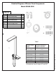
Detailed Diagram of Shower Panel Components Model SCHM-3300 SHCM-3300 Part # Description Qty. 01 Shower Panel Body 1 02 Shower Support Brackets 2 04 Shower Wand Hose 1 05 Hand Shower 1 06 Shower Supply Hose 1 07 Screws M5 x 30 6 08 Wall Anchors 8mm / 5/16” 6 Table 1 SHCM-3053 SHCM-3053 C SHCM-3059 SHCM-3153 SHCM-3168 SHCM-3272 SHCM-3300 Distance between support brackets 35" 33-11/16" 30-3/8" 32-5/16" 34-1/4" 26-1/8" 22-1/16" ©2018 DreamLine.
Product Installation Steps ! BE SURE THAT ALL WATER TO THE SHOWER IS TURNED OFF BEFORE STARTING THIS INSTALLATION 1. The stub-outs for the shower panel should be 1/2” copper pipe, angled down with 90-degree elbows, extending approximately 1-1/2” from the wall, with 1/2” male threaded adapters on the ends. This will make attachment of the unit’s supply lines easier and allow the unit to sit flush against the wall.
3. Assemble the Handshower (#05) and the Shower Supply Hose (#07) according to the diagrams in Fig 3. Fig 3 4. Remove the top panel from the Shower Head assembly (Fig 4.1) Assemble the Shower Head to the Shower Panel Body (#01) using the provided nuts and bolts, according to the diagrams below, then reinstall the top panel (Fig 4.3) shower head Note: Install the bolts from underneath the Shower Panel Body (#01), pushing them up through the holes in the top of the Shower Head portion of the unit (Fig 4.
5. Measure the distance between the bottom edges of the two metal supports on the back of the shower panel (X). This dimension is also provided by the manufacturer on page 10 for comparison. Measure from the bottom of the unit to the bottom of the lower support (D). Using a level, draw two small lines on the wall to indicate the bottom edge of each metal support. (Fig 5) Mark the bottom edge position of upper metal support on wall.
7. Use an assistant to hold the Shower Panel Body (#01), attach the flexible supply lines in the rear of ©2018 DreamLine. All Rights Reserved the unit to the copper stub-outs using thread seal tape. Attach cold water (blue) and hot water (red). Do not overtighten. Hang the unit onto the installed Support Brackets (#02). Turn on the water supply and test the unit for leaks and functionality.
Model Dimensions SHCM-3300 130 mm [5-1/8”] 130 mm [5-1/8”] 1124 mm [44-1/4”] Distance (X) between bottoms of metal supports 1090 mm [43”] 120 mm [4-3/4”] 560 mm [22-1/16”] 1090 mm [43”] 120 mm [4-3/4”] 100 mm [3-15/16”] 140 mm [5-1/2”] 1127 mm [44-1/4”] 441 mm [17-3/8”] Fig 8 ©2018 DreamLine.
Three Critical Steps ! input cold water (blue) input hot water (red) (View from back of unit) Fig 9 1) Be sure the cold water supply line is connected to the cold water end of the control valve (BLUE TAB) and the hot water supply line is connected to the hot water input on the control valve. (RED TAB). 2) Leave the backflow filters in the control valve connections when removing the blue and red tabs.
Shower Panel Functions NOTE: All of the functions shown may not be available for all shower panel models. 1. Top rain shower. (Figure 10) 3. Body sprays. (Figure 12) 4. Hand shower. (Figure 13) DreamLine SHCM-3300 Shower Panel manual Ver 1 07/2018 Figure 11 Figure 12 ©2018 DreamLine. All Rights Reserved 2. Waterfall shower.
Product Maintenance Cleaning materials for faucets and showers: Cleaning Procedures: To avoid damage, it is necessary to use caution when cleaning. Damage caused by improper treatment is not covered under the warranty. Clean your faucets and shower products as necessary. Regular cleaning will prevent limescale buildup and water spotting. To remove limescale, use only products made specifically for that purpose. Always follow the manufacturer’s instructions. Follow the instructions.
Product Maintenance NOTE: If the water in your area contains rust, salt, lime or other minerals or contaminants, you’ll want to inspect your valve assembly regularly. The frequency for this will vary depending on the amount of contaminants in the water. Remove the cartridges and inspect them. Flush them with clean water, using a toothbrush when needed to remove any buildup. Striking the cartridge against the palm of your hand can also help loosen unwanted contaminants.
TEL: 866-731-2244 FAX: 866-857-3638 DREAMLINE.COM For more information on DreamLine® Shower Doors and Enclosures please visit DreamLine.com DreamLine SHCM-3300 Shower Panel manual Ver 1 07/2018 ©2018 DreamLine.