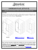
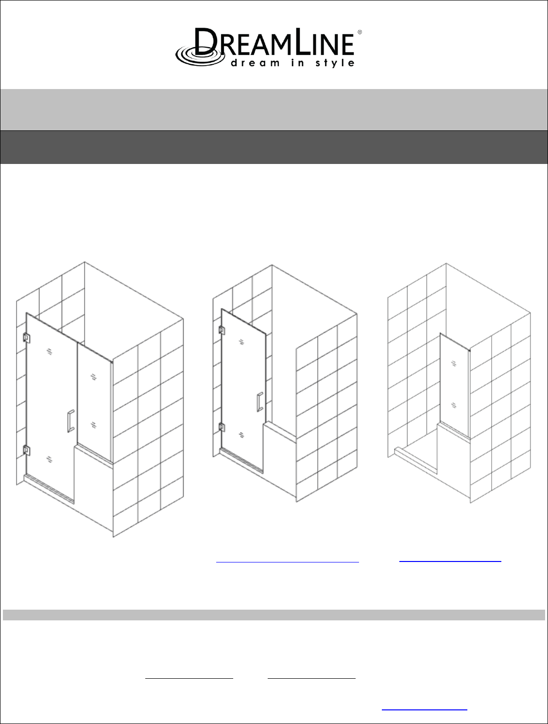
UNIDOOR PLUS (STYLE G) SHOWER DOOR & GLASS PANEL INSTALLATION INSTRUCTIONS IMPORTANT DreamLine® reserves the right to alter, modify or redesign products at any time without prior notice. For the latest up-to-date technical drawings, manuals, warranty information or additional details please refer to your model’s web page on DreamLine.com STYLE G STEP 1: INSTALL SHOWER DOOR STEP 2: INSTALL PANEL Please read these instructions carefully before installing.
UNIDOOR/UNIDOORLUX/UNIDOOR PLUS SINGLE SHOWER DOOR INSTALLATION INSTRUCTIONS IMPORTANT DreamLine® reserves the right to alter, modify or redesign products at any time without prior notice. For the latest up-to-date technical drawings, manuals, warranty information or additional details please refer to your model’s web page on DreamLine.
UNIDOOR STYLES Models with Glass-to-Wall hinges Style C Style B Style A Style E Style F Style J Style I “UNIDOOR” Single Shower Door Ver.2 Rev.
Models with Glass-to-Glass hinge panels: For Glass to Glass hinge Door installation use the installation manual packaged with the Hinge panel glass “UNIDOOR” Single Shower Door Ver.2 Rev.
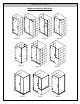
STYLE A UNIDOOR Single shower door 23”- 30” Refer to detailed diagram on page 5 of this manual for assembly instructions STYLE B * UNIDOOR Shower door 23” – 30” with 6” small or 12”-30” large stationary panel STYLE C * UNIDOOR Shower door with 12”-30” large stationary panel STYLE D * UNIDOOR LUX Shower door with 6” small or 14”-30” large stationary panel STYLE E * UNIDOOR LUX Shower enclosure with 30” return stationary panel STYLE F * UNIDOOR PLUS Shower door with 6”-34” in-line stationary panel secured usi
STYLE M3 *^ UNIDOOR Z Shower door 23”~30” with 6” or 24” hinge panel, with 6”, 6-1/2”, 14”, 14-1/2”, 22” or 22-1/2” full height inline panel and 30” - 34” full height return panel secured using u-channel STYLE M4 *^ UNIDOOR Z Shower door 23”~30” with 6” or 24” hinge panel, with 12”, 18”, 24” or 26” in-line buttress panel and 30”- 40” buttress return panel secured using u-channel * For the panel installation instructions, please refer to the separate manual included in the panel glass packaging.
Preparation 1. Prior to installation, examine all boxes and packages for shipping damage and compare the piece count with your packing slip. After opening all boxes and packages read this introduction carefully. Check that all of the needed parts are included in the package by checking off the components on the “Detailed Diagram of Shower Door Components”.
Tools Required “UNIDOOR” Single Shower Door Ver.2 Rev.
“UNIDOOR” Single Shower Door Ver.2 Rev.
“UNIDOOR” Single Shower Door Ver.2 Rev.
“UNIDOOR” Single Shower Door Ver.2 Rev.
Detailed Diagram of Shower Door Components 4 1 31 5 2 6 7 8 Packing List Part# 01 02 04 05 Description Door glass Handle Countersunk screw ST5×70 Hinge with Adjustable angle Qty 1pc 1pc 8pcs 2pcs Part# 06 07 08 31 Description Side strip ( 3 sections to cut) Bottom anti-water strip L-shaped strip PVC hinge spacer Qty 1pc 1pc 1pc 4pcs NOTE: Unpack your unit carefully and inspect it. Lay out and identify all parts using the detailed diagram and packing list in this manual as a reference.
Single Shower Door Assembly and Installation NOTE: The following shower door installation instructions should be used as a general guide and prerequisite to the installation of the UNIDOOR, UNIDOORLUX and UNIDOOR PLUS models. Before you begin the installation, please check your finished opening size. Specific size information can be found on our website at DreamLine.
2. The Door Glass (01) ships with four 5/8” shims attached to the top (2pcs) and bottom (2pcs). Determine the swing of your door and only remove the shims from the top of the door glass, leaving the bottom shims in place. Set the Door Glass (01) onto the threshold at the desired location and check for level. These 5/8” shims will leave the proper spacing at the bottom of the door glass and will ensure that the door height finishes at 72”, but always confirm with a measurement.
1 TIP: The PVC hinge spacer can also be used as a template to assist with marking the hinge mounting holes. 2 3 Fig. 4 ATTENTION: The back plate of the hinge from inside the shower locates too close to the drilled holes in the wall and might get scratched by the long screws or screwdriver. Be careful not to scratch the hinge surface. (OPTIONAL) 4. Carefully remove back plates from the Hinges (05) and set the Door Glass (01) aside.
Setting the Adjustable Hinges The Adjustable hinges are pre-set to overclose to 85º and are adjustable up to 90º after the door is installed. Once the door glass is installed, simply loosen the allen set screws and position the door to the desired closed position. While holding the door in the new closed position, retighten the allen screws and your door will now self-center to the chosen closed position. 4a.
4b. The hinges are factory set to 85 degrees. You can change this angle by using the adjustment screws on the hinge plate. (Figure 5b) inside outside Figure 5b 4c. Use the supplied Allen Key to loosen the adjustment screws on the inside hinge plate, adjust the door to the desired angle (90 degrees for example) then retighten the adjustment screws (Figure 5c). Be sure that you create a tight seal with the supplied strike vinyl when the door is in the closed position.
5. Mount the Handle (02) to the Door Glass (01). See Fig. 6 for details. NOTE: DO NOT attach the handle to the door glass until instructed to do so. DO NOT use the handle to lift the glass during installation. This may result in damage to the glass and/or serious injury. Always use an assistant or a professional grade glass suction cup when handling the door glass. Fig. 6 6. Measure the bottom of the Door Glass (01) from end to end to determine the actual width of the door.
1 Into the hinge Into the hinge 3 4 7/8" 7/8" Into the hinge 5 See Fig. 8 for details 2 7/8" 7. Get three measurements: from the top edge of the Door Glass (01) to the upper body of the top Hinge (05) (+) 7/8” from the lower body of the upper Hinge to the upper body of the bottom Hinge (+) 1-3/4” from the lower body of the bottom Hinge to top of the installed Bottom anti-water strip (07) (+) 1-7/8” Cut the Side strip (06) according to the measurements.
Fig. 10 “UNIDOOR” Single Shower Door Ver.2 Rev.
Style “A”: Half Etched Glass Installation NOTE: This model features the half etched glass option. Hinged Left installation shown. To install for hinged Right, flip the door to the proper handing. -The textured surface of the glass door should face out. See Fig. 11 for details. Fig. 11 “UNIDOOR” Single Shower Door Ver.2 Rev.
Product Maintenance BASES and BACKWALLS: To ensure long lasting life for your acrylic back walls: wipe them off after each use with a soft cloth. To clean the acrylic back walls use non-abrasive sprays or cream based cleaners. Avoid the use of aerosol spray cleaners. Never use abrasive cleansers, metal brushes or scrapers that could scratch or dull the surface. GLASS: To ensure long lasting life for your glass shower products: wipe them off after each use with a soft cloth.
TEL: 866-731-2244 FAX: 866-857-3638 DREAMLINE.COM For more information on DreamLine® Shower Doors and Enclosures please visit DreamLine.
UNIDOOR (STYLE G) SHOWER DOOR GLASS PANEL INSTALLATION INSTRUCTIONS IMPORTANT DreamLine® reserves the right to alter, modify or redesign products at any time without prior notice. For the latest up-to-date technical drawings, manuals, warranty information or additional details please refer to your model’s web page on DreamLine.com Style G Right side panel installation shown Please read these instructions carefully before installing.
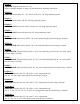
Model #s SHDR-24232434-## SHDR-24232436-## SHDR-24233634-## SHDR-24233636-## SHDR-24242434-## SHDR-24242436-## SHDR-24243634-## SHDR-24243636-## SHDR-24273034-## SHDR-24273036-## SHDR-24273634-## SHDR-24273636-## SHDR-24283034-## SHDR-24283036-## SHDR-24283634-## SHDR-24283636-## SHDR-24293034-## SHDR-24293036-## SHDR-24293634-## SHDR-24293636-## SHDR-24303034-## SHDR-24303036-## SHDR-24303634-## SHDR-24303636-## Style G ## = finish 01 – Chrome 04 – Brushed Nickel 06 – Oil Rubbed Bronze “UNIDOOR (STYLE
ADDITIONAL MODEL CONFIGURATIONS for UNIDOOR- X GLASS-TO-GLASS HINGE DOORS Model #s D3242436R-## D3242436L D3242434R D3242434L D3232436R D3232436L D3232434R D3232434L D1303636 D1303634 D1303036 D1303034 D1302436 D1302434 D1293636 D1293634 D1293036 D1293034 D1292436 D1292434 D1283636 D1283634 D1283036 D1283034 D1282436 D1282434 D1273636 D1273634 D1273036 D1273034 D1272436 D1272434 D1263636 D1263634 “UNIDOOR (STYLE G)” Ver 1 Rev 5 06/2016 D1263036 D1263034 D1262436 D1262434 D1253636 D1253634 D1253036 D12530
Preparation 1. Prior to installation, examine all boxes and packages for shipping damage and compare the piece count with your packing slip. After opening all boxes and packages read this introduction carefully. Check that all of the needed parts are included in the package by checking off the components on the “Detailed Diagram of Shower Door Components”.
Tools Required Caulk Level Tape Measure Caulk Gun “UNIDOOR (STYLE G)” Ver 1 Rev 5 06/2016 Pencil Electric Drill Phillips Screwdriver Hammer Mallet Drill bit (Ø=5/16") Drill bit (Ø=1/8") Wood Miter saw 5
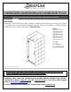
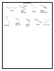
Detailed Diagram of Glass Panel Components 13 11 9 23 28 29 8 Packing List 08 09 11 13 L-shaped strip * U-channel 1 (76”, wall profile) Stationary glass Ø5/16” Wall anchor 1pc 23 1pc 28 1pc 29 14pcs Countersunk screw ST4.2x40 Adjustment spacer U-channel 2 (44”, bottom profile) 14pcs 6pcs 1pc NOTE: Unpack your unit carefully and inspect it. Identify all parts using the detailed diagram and packing list in this manual as a reference.
Style “G”: 6”-34” In-Line Half Wall Stationary Panel Installation NOTE: The Unidoor shower door needs to be installed prior to proceeding with the following Stationary Glass installation instructions. Please see the Single Shower Door installation manual included in the door packaging for complete shower door installation instructions. Before you begin the installation, please recheck your shower opening size. Specific size information can be found on our website at DreamLine.
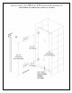
NOTE: Use parts from “Detailed Diagram of Glass Panel Components” for the Stationary Glass assembly and installation. 2. Measure the actual width and height of your Stationary glass (11). See Fig. 2 for details. H Fig. 2 3. NOTE: You will be doing straight cuts for this stationary panel installation. W *It may be necessary to remove any burrs from the cut end of the U-channels with a metal file before placing the U-channel onto the glass.
H (+) 1" b) Fig. 4 4. Slip the cut U-channel 2 (bottom profile) (29) and U-channel 1 (wall profile) (09) onto the Stationary glass (11) in the shown locations. With the door open, place the Stationary glass on the half wall ledge opposite of door. Adjust the Stationary glass and U-channel 1 (wall profile) against the wall to compensate for any out of plumb conditions ensuring that the Stationary glass is level vertically and U-channel 1 is flush with the wall.
5. While securely holding the Stationary glass (11), close the Glass Door and align the Stationary glass to it. Use the door mark on the ledge as a reference to ensure that the Door is perpendicular to the wall. 2 1 outside Stationary glass Door inside 1/8"-3/16" NOTE: The top of the Stationary glass must be leveled with the Glass door. By traversing across the top of both the Stationary glass and door, height differences can be measured.
6. Remove the U-Channel 2 (bottom profile) (29) and U-channel 1 (wall profile) (09) from the Stationary glass (11). Carefully set the Stationary glass aside. See Fig. 8 for details. U-channel 1 U-channel 2 Fig. 8 7. Place the c u t U-Channel 2 (bottom profile) (29) onto the ledge in line with the inside mark. Mark the drill holes on the ledge through the predrilled holes in the U-Channel 2 and drill the holes using Ø5/16” drill bit. Insert the Ø5/16” Wall anchors (13).
Fig. 10 8. Cut the U-channel 1 (wall profile) (09) at the top mark that was made in step #5. Place the U-Channel 1 (wall profile) on the U-Channel 2 (bottom profile) (29) and align vertically with the inside wall mark. Mark the drill holes on the wall through the predrilled holes in the U-Channel 1. 1 U-Channel 1 2 U-Channel 2 3 Now drill holes in the wall using Ø5/16 drill bit and insert the Ø5/16” Wall anchors (13). 4 Ø5/16” 5 See Fig. 11 for details. Fig.
9. Apply waterproof silicone along the bottom surface and around the holes of the UChannel 1 (wall profile) (09). Fasten the U-Channel 1 to the wall with the Countersunk screw ST4.2x40 (23). Insert the provided Adjustment Spacers (28) into U-Channel 2 (bottom profile) (29) for minor adjustments if necessary. Apply Waterproof silicone into the groove of both U-Channels. NOTE: The surface needs to be clean and free of debris before applying silicone. 1 3 waterproof silicone 2 4 5 See Fig.
10. Slide the Stationary glass (11) into the groove of both U-Channels. Apply a bead of silicone on the open end of the U-Channel, and its connection. Ensure that the silicone applied to the open end is flat and smooth so that it will not interfere with the installation of the Lshaped strip*(08) in step #12. NOTE: If you have difficulty sliding the Stationary glass into the U-Channels, you can slightly tap on the Stationary glass with a rubber mallet and a piece of wood.
11. Apply a good quality mildew resistant waterproof silicone along the connection of both U-Channels to the wall and ledge on the inside of shower. See Fig. 16 for details. waterproof silicone ATTENTION: Prior to the next step, please be sure the part of the wall and glass edge for installation of the L-shaped strip*(08) is clean, dry and free from soap, oil and any construction debris. 12.
Product Maintenance BASES and BACKWALLS: To ensure long lasting life for your acrylic back walls: wipe them off after each use with a soft cloth. To clean the acrylic back walls use non-abrasive sprays or cream based cleaners. Avoid the use of aerosol spray cleaners. Never use abrasive cleansers, metal brushes or scrapers that could scratch or dull the surface. GLASS: To ensure long lasting life for your glass shower products: wipe them off after each use with a soft cloth.
TEL: 866-731-2244 FAX: 866-857-3638 DREAMLINE.COM For more information on DreamLine® Shower Doors and Enclosures please visit DreamLine.