AQUA T UB D OOR AND T UB D OOR G LASS P ANEL I NSTALLATION I NSTRUCTIONS IMPORTANT DreamLineTM reserves the right to alter, modify or redesign products at any time without prior notice. For the latest up-to-date technical drawings, manuals or any other details please refer to the support.BathAuthority.com web page.
AQUA SHOWER / TUB DOOR INSTALLATION INSTRUCTIONS IMPORTANT DreamLineTM reserves the right to alter, modify or redesign products at any time without prior notice. For the latest up-to-date technical drawings, manuals or any other details please refer to the support.BathAuthority.com web page. Please read these instructions carefully before installing.
Preparation 1. After opening all boxes and packages, read this introduction carefully. Check that all of the needed parts are included in the package by marking all the components on the “Detailed Diagram of Shower Door Components”. Examine boxes and packages for shipping damage. If the unit has been damaged, has a finishing defect, or is missing parts, please contact our customer support department within 5 business days of the delivery date.
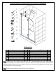
Detailed Diagram of Shower Door and Tub Door Component 1 7 8 9 3 2 4 5 10 11 6 12 13 14 15 Packing List 01 02 03 04 05 06 07 08 Wall profile Stationary glass Support bar Hinge Glass door Towel bar Wall anchor Decorative caps 1pc 1pc 1pc 2pcs 1pc 1pc 5pcs 2pcs 09 10 11 12 13 14 15 Round Head screw ST4.2×10 Big head screw ST4.2×40 Anti-Water strip Bottom anti-water strip Round head screw ST4.2×25 Bottom bracket Countersunk screw ST4.
Shower/Tub Door Installation 1. Place the Wall profile (01) to the wall above the shower base or tub and level it vertically. See Fig. 1 for details. Fig. 1 2. Mark the drilling holes on the wall through the holes in the Wall profile (01). Place the Wall profile aside, drill the holes using Ø5/16” drill bit and insert the Wall anchors (07). Apply silicone caulk along the wall profile and around the holes on the wall.
3. Slide the Stationary glass (02) into the groove of the Wall profile (01). See Fig. 3 for details Fig. 3 4. Take apart the Bottom bracket (14). Place the Bottom bracket base into the notch on the bottom of the Stationary glass (02) from inside and mark the drill hole on the threshold, tray or bathtub. Remove the glass, drill the hole using Ø1/8” drill bit and secure the Bottom bracket base with Round head screw ST4.2×25 (13). See Fig. 4 for details. 1 3 Inside Ø1/8" Outside 2 4 Fig. 4 “AQUA” Rev.
5. Place the Stationary glass (02) back into the Wall profile (01) and assemble the Bottom bracket (14). See Fig. 5 for details. NOTE: Make sure to use clear rubber gasket to prevent glass to metal connection. Fig. 6 Fig. 5 6. Locate the Support bar (03). Adjust the Support bar at the angle that will provide adequate support to the glass and the wall. Level it horizontally. Hold it firmly and outline the bracket’s position on the wall. Remove the Support bar and detach the wall bracket from it.
7. Install both Hinges (04) on the Stationary glass (02) with the decorative non-screw side facing outwards. Hang the Glass door (05) from the inside. You will need assistance in this process. NOTE: Use 5/8” shim beneath the glass door to hold it in position while you attach the hinges. NOTE: Use clear rubber gasket to prevent glass to metal connection. Inside Outside 1 Begin at the top hinge when hanging the door.
8. Install the Towel bar (06) onto the Glass door (05). Attach the Anti-water strip (11) over the vertical edge of the Glass door (05). Attach the Bottom anti-water strip (12) over the bottom edge of the Glass door. 1 3 Door Outside Inside Outside See Fig. 9 for details. 2 Inside Panel Outside Door Fig. 9 9.
. Apply caulk inside and outside along bottom and vertical edge of the stationary glass and wall profile. See Fig. 11 for details. Caulk Fig. 11 Product Maintenance To ensure long lasting life for your acrylic back walls, wipe them off after each use with a soft cloth. To clean the acrylic back walls use non-abrasive sprays or cream based cleaners. Never use abrasive cleansers, metal brushes or scrapers that could scratch or dull the surface.
AQUA SERIES TUB EX/RT TUB DOOR GLASS PANEL INSTALLATION INSTRUCTIONS MODEL: __________ STYLE: __________ SELECTOR: __________ Please choose your door model, style and selector according to your order for easy installation. IMPORTANT DreamLineTM reserves the right to alter, modify or redesign products at any time without prior notice. For the latest up-to-date technical drawings, manuals or any other details please refer to the support.BathAuthority.com web page.
Preparation 1. After opening all boxes and packages, read this introduction carefully. Check that all of the needed parts are included in the package by marking all the components on the “Detailed Diagram of Glass Panel Components”. Examine boxes and packages for shipping damage. If the unit has been damaged, has a finishing defect, or has missing parts, please contact our customer support department within 5 business days of the delivery date.
Detailed Diagram of Glass Panel Components Packing List 01 02 07 U-channel 1 (wall profile) U-channel 2 (bottom profile) Ø5/16” Wall anchor 01 02 07 U-channel 1 wall profile) U-channel 2 (bottom profile) Ø5/16” Wall anchor Diagram A 1pc 08 Countersunk screw ST4.2x40 1pc 10 Countersunk screw ST4.2x25 4pcs 16 Extender panel glass Diagram B 1pc 08 Countersunk screw ST4.2x40 1pc 10 Countersunk screw ST4.
Configuration 2: 9” In-Line Extender Panel Installation NOTE: The following installation instructions apply to all of the Aqua series tub doors. Please install whichever Aqua model you purchased prior to proceeding with the following Stationary Glass installation instructions. Please see the Shower / Tub Door Installation manual included in the door packaging for complete tub door installation instructions. NOTE: The “Standard” Aqua Hinged Tub Door is the example shown throughout this installation manual.
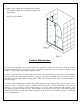
2. Remove the U-channel 1 (wall profile) (01) and Uchannel 2 (bottom profile) (02) from the Extender panel glass (16) and carefully set the Extender glass aside. Place the U-Channel 2 (bottom profile) onto the tub ledge in line with the inside U-channel mark. 1 wall inside U-channel 1 U-channel 2 outside Mark the drill holes on the tub ledge through the predrilled holes in the U-Channel 2 and drill the holes using Ø1/8” drill bit.
3. Place the U-Channel 1 (wall profile) (01) on the UChannel 2 (bottom profile) (02) and align vertically with the inside U-channel wall mark. Mark the drill holes on the wall through the predrilled holes in the U-Channel 1. Now drill holes in the wall using Ø5/16 drill bit and insert the Ø5/16” Wall anchors (07). Apply waterproof silicone along the bottom surface and around the holes of the U- Channel 1 and fasten it to the wall with the Countersunk screws ST4.2×40 (08).
4. Apply Waterproof silicone into the groove of both U-Channels. waterproof silicone NOTE: The surface needs to be clean and free of debris before applying silicone. 1 See Fig. 6 for details 2 Fig. 6 5. Slide the Extender panel glass (16) into the groove of both U-Channels. 1 2 3 4 NOTE: If you have difficulty sliding the Extender panel glass into the U-Channels, you can slightly tap on the Extender glass with a rubber mallet and a piece of wood.
Fig. 8 6. Apply waterproof silicone along the connection of both U-Channels to the wall and tub ledge on the inside of shower. See Fig. 9 for details. waterproof silicone inside Fig. 9 “AQUA SERIES TUB EX/RT”, PANEL Rev.1 Ver.
Configuration 3: 30” Return Panel Installation NOTE: The following installation instructions apply to all of the Aqua series tub doors. Please install whichever Aqua model you purchased prior to proceeding with the following Return Glass installation instructions. Please see the Shower / Tub Door Installation manual included in the door packaging for complete tub door installation instructions. NOTE: The “Standard” Aqua Hinged Tub Door is the example shown throughout this installation manual.
8. Place the U-Channel 2 (bottom profile) (02) onto the tub ledge in line with the inside U-channel mark. Mark the drill holes on the tub ledge through the predrilled holes in the U-Channel 2 and drill the holes using Ø1/8” drill bit. Apply waterproof silicone along the bottom surface and around the holes of the U- Channel 2 and fasten it to the tub ledge with the Countersunk screws ST4.2×25 (10).
9. Place the U-Channel 1 (wall profile) (01) on the UChannel 2 (bottom profile) (02) and align vertically with the inside U-channel wall mark. Mark the drill holes on the wall through the predrilled holes in the U-Channel 1. Now drill holes in the wall using Ø5/16 drill bit and insert the Ø5/16” Wall anchors (07). Apply waterproof silicone along the bottom surface and around the holes of the U- Channel 1 and fasten it to the wall with the Countersunk screws ST4.2×40 (08).
10. Apply Waterproof silicone into the groove of both U-Channels. waterproof silicone NOTE: The surface needs to be clean and free of debris before applying silicone. 1 See Fig. 15 for details 2 Fig. 15 11. Slide the Return panel glass (17) into the groove of both U-Channels. 1 2 3 4 NOTE: If you have difficulty sliding the Return panel glass into the U-Channels, you can slightly tap on the Return glass with a rubber mallet and a piece of wood.
Fig. 17 12. Apply waterproof silicone along the connection of both U-Channels to the wall and tub ledge on the inside of shower. See Fig. 18 for details. waterproof silicone inside Fig. 18 “AQUA SERIES TUB EX/RT”, PANEL Rev.1 Ver.
Maintenance To ensure long lasting life for your acrylic back walls, wipe them off after each use with a soft cloth. To clean the acrylic back walls use non-abrasive sprays or cream based cleaners. Never use abrasive cleansers, metal brushes or scrapers that could scratch or dull the surface. To ensure long lasting life for your glass shower products, wipe them off after each use with a soft cloth. Rinse and wipe of the glass using either soft cloth or squeegee to prevent soap buildup.
DREAMLINE™ EXCLUSIVE LIMITED WARRANTY AS OF MAY 6, 2013 This warranty extends only to the original owner/end‐user for household use only and is not transferable to a subsequent owner. This warranty extends for a designated period of time, so long as it remains in use in its original place of installation. This warranty applies only to DreamLine products purchased from an authorized dealer in United States or Canada.
TEL: 866-731-2244 FAX: 866-227-1533 WWW.BATHAUTHORITY.COM For more information on DreamLineTM Shower Doors and Enclosure please visit www.BathAuthority.com “AQUA SERIES TUB EX/RT”, PANEL Rev.1 Ver.