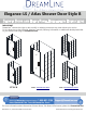
Elegance-LS / Atlas Shower Door Style B SHOWER DOOR AND INLINE PANEL INSTALLATION INSTRUCTIONS IMPORTANT DreamLine® reserves the right to alter, modify or redesign products at any time without prior notice. For the latest up-to-date technical drawings, manuals, warranty information or additional details please refer to your model’s web page on DreamLine.
ELEGANCE / ELEGANCE-LS / ATLAS SINGLE DOOR SINGLE SHOWER DOOR INSTALLATION INSTRUCTIONS IMPORTANT DreamLine® reserves the right to alter, modify or redesign products at any time without prior notice. For the latest up-to-date technical drawings, manuals, warranty information or additional details please refer to your model’s web page on DreamLine.
This model is treated with DreamLine’s exclusive ClearMaxTM Glass technology. This is a specially formulated coating that prevents the buildup of soap and water spots. Install the surface with the ClearMaxTM label towards the inside of the shower. Please note that depending on the model, the glass may be coated on either one or both surfaces. For best results, squeegee the glass after each use and dry with a soft cloth.
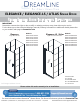
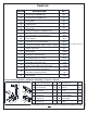
Table of Contents Page # Section title Configurations 2 Preparation Tools 3 Parts List 5-6 Adjustable Wall Profile System 7 Installation Steps 8-18 Pivot Assembly Vinyl Seals 9-10 13 Product maintenance 19 4 Example: Elegance-LS / Atlas Left-Swing door installation ! Right-Swing door installation NOTE: This door is reversible for right or left-swing door installation. The left-swing door installation is shown as an example throughout this manual.
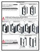
Configurations This manual will describe the single door installation of the Elegance or Elegance-LS/Atlas models. For models with additional panel glass, use this manual first to install the door and then use the manual that is packaged with the panel glass to install the panel.
Preparation 1. Prior to installation, examine all boxes and packages for shipping damage and compare the piece count with the packing slip. After opening all boxes and packages read this introduction carefully. Check that all of the necessary parts are included in the package by checking off the components on the “Detailed Diagram of Shower Door Components”.
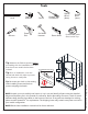
Tools Level Silicone Tape Measure Power Drill Pencil Soft Head Hammer Phillips Screwdriver Drill bit Ø5/16" (8mm) Drill bit Ø1/8" (3mm) Professional grade Glass suction cup Razor Knife Top Tip: Measure the finished opening before proceeding with the installation to be sure that the correct model size has been ordered. Threshold must be level. Middle Tip: Prior to installation, cover the shower/tub drain with tape to prevent losing screws or small parts. ! W ©2018 DreamLine.
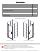
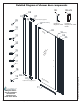
Detailed Diagram of shower door components 08 01 02 09 06-LS 06 07 top left or bottom right pivot 10(x70-11/16”) 12 Handle for Elegance model 03 to p 13 Handle for Elegance-LS / Atlas model 10(x72”) 04 05 14 15 16 17 18 08 07 ©2018 DreamLine.
Parts List QTY DESCRIPTION PART# 01 Wall profile for Pivot side 1pc 02 Glass profile for Pivot side 1pc 03 Door glass 1pc 04 Glass profile 1pc 05 Wall profile 1pc Handle (Elegance / Elegance-LS) 1set 07 Pivot assembly (top and bottom) 1pair 08 Pivot retainer 2pcs 09 Decorative cover with washer 8pcs 10 * Snap-in Anti-water strip (1 long / 1 short) 2pcs 11 Sweep Vinyl seal 1pc 12 Wall anchor 12pcs 13 Bolt M4x16 (with washer) 4pcs 14 Pan head screw ST4.
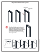
Adjustable Wall Profile System Glass Profile Wall Profile 1” m ! her Ø1/8" was w 3 dec ora scre cap 2 ©2018 DreamLine. All Rights Reserved The Glass Profiles can be adjusted within the Wall Profiles for overall width or to correct for out-of-plumb conditions within the model size. Screw them together after making final adjustments.
Installation steps ! The Elegance-LS / Atlas Left-Swing door installation is shown as an example throughout this manual. 1 ! 2** NOTE: If this door is to be part of an enclosure model, refer to the model size table in the enclosure panel glass manual for the correct placement of the door glass to match the enclosure size. Ø5/16” 1. Position the Wall Profile for Pivot Side (#01) 3** onto the threshold and against the desired hinge-side wall and adjust to plumb.
2. Separate the Pivot Retainers (#08) from the Pivot Assemblies (#07) by removing the Round Head Socket Bolt M6×12 (#17). Insert the Pivot Retainers (#08) into both ends of the Wall Profile for Pivot Side (#01). (Fig 2) 1 2 3 4 Fig 2 top left/ bottom right pivot shown as viewed from outside 3. Run a bead of silicone along the holes on the wall and on the back of the Wall Profile for Pivot Side (#01).
! NOTE: The Glass Profile for Pivot Side (#02) is shorter and has an additional pair of holes at each end for the Pivot Assembly (#07). These extra holes are not present in the Glass Profile (#04) that is used for the strike side/panel side. 1 outside 4. Attach the Pivot Assemblies (#07) to the top and the bottom ends of the Glass Profile for Pivot Side (#02) with the Flat Head Screws ST4.2×25 (#15) and M4×16 bolts and washers (#13).
! NOTICE: The Door Glass (#03) has a top and a bottom notch for the pivots. The notch at the top is deeper and the notch at the bottom is shallower (to allow space for the bottom sweep vinyl). Identify this difference to prevent installing the Door Glass upside-down. See Pivot Assembly parts list on Page 6 for reference 6. Remove the Bolts (L) and Back Plates (K) from the top and bottom Pivot Assemblies (#07). Position the Door Glass (#03) onto the Pivot Assemblies (#07).
8. Open the Door Glass (#03) to expose the bottom Pivot Retainer (#08). (Fig 8) Fig 8 ! NOTE: Sealing the hole in the bottom Pivot Retainer is important. Screwing the bottom Pivot Retainer to the threshold is optional. 9. Seal the unused hole in the bottom Pivot Assembly (#07) with the Flat Head Socket Bolt M6×12 (#18) OR attach the Pivot Retainer (#08) to the Shower base or threshold by drilling an Ø1/8” hole and using a Large Truss Head Screw ST4.2×40 (#16).
10. Firmly push the shorter Snap-In Anti-Water Strip (#10) into the vertical groove of the Glass Profile for Door Glass (#02). (Fig 10) 1 2 do inside or 3 do or door hinge side outside outside outside Fig 10 ! NOTE: ◾ When installing the single door model, use both of the Snap-In Anti-Water Strips (#10) (Fig 10 & Fig 11) included with the Door Glass that snap into the Glass Profiles, (snap the shorter one into the hinge side glass profile and the longer one into the strike side glass profile).
11. Push the Glass Profile (#04) into the Wall Profile (#05) and snap the longer Anti-Water Strip (#10) into the Glass Profile (#04). (Fig 11) 1 ©2018 DreamLine.
12. Hold the Door Glass (#03) in the closed position, parallel to the threshold. Adjust the Glass Profile (#04) within the Wall Profile (#05) and adjust the position of the Wall Profile (#05) on the wall to ensure that the Door Glass (#03) makes tight contact with the flange of the Anti-Water Strip (#10) from top to bottom. Use a level to ensure that the Door Glass (#03) and the Wall Profile (#05) are plumb, but make sure that the door glass makes full contact with the strike vinyl.
13. Apply silicone to the back of the Wall Profile (#05) and around the holes in the wall. Install the Wall Profile (#05) to the wall using the Large Truss Head Screws ST4.2×40 (#16). Slide the Glass Profile (#04) back into the Wall Profile (#05). (Fig 13) 1 2 ©2018 DreamLine.
14. Adjust the overall width of the Door using the Glass Profiles (#02 and #04) on one or both sides of the opening. Slide the Glass Profiles out of the Wall Profiles up to 1” per side as necessary to maintain a 1/16" - 1/8" reveal between the Door Glass (#03) and the Anti-Water Strip (#10). (Fig 14.2) Hold the top of the Door Glass (#03) level and tighten the pivot assembly in place with the Round Head Socket Bolt M6×12 (#17) (Fig 14.3). Test the operation of the door before proceeding to the next step.
16. Cut the Sweep Vinyl Seal (#11) to the width of the Door Glass (#03). Next, trim the Sweep Vinyl Seal (#11) to size up to the bottom pivot. Close the door and notch off the deflector on the inner side of the Sweep Vinyl Seal (#11) where it overlaps the strike vinyl when the door is closed (Fig 16.3). Press the Sweep Vinyl Seal (#11) tightly onto the bottom edge of the Door Glass (#03). (Fig 16) 2 1 4 3 5 3/8” (+/-) Fig 16 17.
Product Maintenance BASES and BACKWALLS: To ensure long-lasting life for your acrylic back walls, wipe them off after each use with a soft cloth. To clean the acrylic back walls use non-abrasive sprays or cream based cleaners. Avoid the use of aerosol spray cleaners. Never use abrasive cleansers, metal brushes or scrapers that could scratch or dull the surface. GLASS: To ensure long-lasting life for your glass shower products, wipe them off after each use with a soft cloth.
TEL: 866-731-2244 FAX: 866-857-3638 DREAMLINE.COM For more information on DreamLine® Shower Doors and Enclosures please visit DreamLine.com ©2018 DreamLine.
INLINE PANEL - STYLE B INLINE PANEL INSTALLATION INSTRUCTIONS IMPORTANT DreamLine® reserves the right to alter, modify or redesign products at any time without prior notice. For the latest up-to-date technical drawings, manuals, warranty information or additional details please refer to your model’s web page on DreamLine.
Model #s UNIDOOR - Style B w/ 6” inline UNIDOOR - Style B inline w/L-Bar™ MODEL #s MODEL #s SHDR-20297210-## SHDR-20307210-## SHDR-20317210-## SHDR-20327210-## SHDR-20337210-## SHDR-20347210-## SHDR-20357210-## SHDR-20367210-## UNIDOOR - Style B inline w/ Support Bar MODEL #s SHDR-20417210C-## SHDR-20427210C-## SHDR-20437210-## SHDR-20447210-## SHDR-20457210-## SHDR-20467210-## SHDR-20477210-## SHDR-20487210-## SHDR-20477210C-## SHDR-20487210C-## SHDR-20497210-## SHDR-20507210-## SHDR-20517210-## SHDR
This model is treated with DreamLine’s exclusive ClearMaxTM Glass technology. This is a specially formulated coating that prevents the buildup of soap and water spots. Install the surface with the ClearMaxTM label towards the inside of the shower. Please note that depending on the model, the glass may be coated on either one or both surfaces. ©2018 DreamLine. All Rights Reserved For best results, squeegee the glass after each use and dry with a soft cloth.
Table of Contents Page # Preparation Tools 2 Detailed Diagram of Shower Panel Components Parts List 4 5 Adjustable Wall Profile System 6 Installation Steps 7-16 Vinyl Seals 9 Support Bar Installation 13 L-Bar Assembly 14 Product maintenance 17 Left-side inline panel installation ! 3 Right-side inline panel installation NOTE: This model is reversible for right or left-side panel installation. The right-side panel installation is shown as an example throughout this manual.
Preparation 1. Prior to installation, examine all boxes and packages for shipping damage and compare the piece count with the packing slip. After opening all boxes and packages read this introduction carefully. Check that all of the necessary parts are included in the package by checking off the components on the “Detailed Diagram of Shower Panel Components”.
Tools Level Tape Measure Power Drill Phillips Screwdriver Knife Professional-grade Glass suction cup Pencil Silicone Drill bit (Ø5/16") (8mm) Drill bit (Ø1/8") (3mm) Soft Head Hammer Mallet Top Tip: Measure the finished opening before proceeding with the installation to be sure that the correct model size has been ordered. Threshold must be level shower/tub drain with tape to prevent losing screws or small parts.
Detailed Diagram of Shower Panel components Diagram A 12* 11 10 Diagram B 11 9 10 13 13 14 14 15 15 16 16 17 17 18 18 19 19 9 12a Right L-Bar™ (installation shown) 12b Left L-Bar™ 23 Right side panel installation shown (using Right L-Bar™) ©2018 DreamLine.
Parts List Diagram A PART# DESCRIPTION QTY PART# DESCRIPTION QTY 09 Wall profile 1pc 15 Truss head screw ST4.2x40 4pcs 10 Glass profile 1pc 16 Pan head screw ST4.2x35 1pc 11 Panel glass 1pc 17 Decorative screw cover and washer 4pcs 12* Support bar * 1pc 18 Bottom bracket 1pc 13 Wall Anchor 4pcs 19 Anti-Water strip (inline) 1pc 14 Pan head screw ST4.2x10 3pcs 23 Countersunk screw ST4.
Adjustable Wall Profile System Glass Profile Wall Profile 1” m The Glass Profiles can be adjusted within the Wall Profiles for overall width or to correct for out-of-plumb conditions within the model size. Screw them together after making final adjustments. her 3 Ø1/8" was w scre 2 dec ora tive cap 1 ©2018 DreamLine.
Installation steps NOTE: The UNIDOOR or ELEGANCE shower door ! needs to be installed prior to proceeding with the following Panel Glass installation. Please see the Single Shower Door installation manual included in the door packaging for complete shower door installation instructions. Before beginning the installation, recheck the finished opening size. Specific model size information can be found on DreamLine.com.
2. Apply clear silicone into the entire length of the channel of the Glass Profile (#10) and attach it to the edge of the Panel Glass (#11). Make sure the Glass Profile (#10) is flush with the top and bottom of the Panel Glass (#11). Insert the Panel Glass (#11) with the attached Glass Profile (#10) into the Wall Profile (#09). (Fig 2) ! ATTENTION: Please note that the bottom hole in the corner of the Panel Glass must be opposite from the Glass Profile.
3. Press the Anti-Water Strip (inline) (#19) onto the vertical edge of the Panel Glass (#11). (This will protect the edge of the panel glass and allow for proper spacing with the door glass). Attach the Bottom Bracket (#18) through the bottom hole of the Panel Glass (#11). (Fig 3) 1 inside 2 3 inside 4 inside inside Fig 3 4. Carefully position the assembled panel onto the threshold and against the wall. Push the Wall Profile (#09) tight to the wall while holding the panel tight to the threshold.
5. Close the Door and align the Panel Glass (#11) with the Door. Use the reference mark on the threshold (from Step #1 ) to confirm that the Door is perpendicular to the wall. If necessary, adjust the position of the Panel Glass (#11) so that the Anti-Water Strip (inline) (#19) makes contact with the Door Glass from top to bottom and creates a seal. ◾Mark the wall along the inner edge of the Wall Profile (#09). ◾Mark the drilling hole onto the threshold through the hole in the Bottom Bracket (#18).
! Double check the alignment and spacing of the panel glass with the door glass before drilling into the threshold for the bottom bracket. 7. Drill a hole for the Bottom Bracket (#18) into the threshold at the mark that was made in Step #5. ** Use an Ø1/8” drill bit for installation into an acrylic base OR use a Ø5/16” drill bit and an anchor for installation into a tile threshold. Use the Pan Head Screw ST4.
8. Recheck the alignment and spacing of the Door Glass and Panel Glass (#11) and test the operation of the Door. After final adjustments of the Panel Glass (#11) drill holes into the Glass Profile (#10) through the predrilled holes in the Wall Profile (#09) using an Ø1/8” drill bit. Use the Pan Head Screws ST4.2×10 (#14) and Washers (#17) to attach the Wall Profile (#09) to the Glass Profile (#10). Cover the exposed screw heads with Decorative Screw Cover (#17).
Support Bar Assembly and Installation 10. Attach the Support Bar (#12) to the Panel Glass as shown. ◾ Adjust the Support Bar (#12) to a proper position on the glass and the wall (ideally at a 45° angle) and level it. ◾ Outline the Wall Bracket’s position on the wall Fig 10.2. ◾ Remove the Wall Bracket from the Support Bar (#12). ◾ Place the Wall Bracket against its outlined position on the wall and mark the hole for drilling.
L-Bar™ Parts List Assembly (Right L-Bar™ shown) Right L-Bar™ installation shown as an example 4.9 4.4 4.3 4.5 4.2 4.6 4.1 4.7 4.8 Unidoor-LS -Style B DESCRIPTION QTY PART# DESCRIPTION QTY 4.1 PVC spacer 2pcs 4.6 Wall Plate 1pc 4.2 M5 rubber tip set screw 2pcs 4.7 Truss Head Screw ST4.2x40 2pcs 4.3 L-Bar™(Right-hand shown) 1pc 4.8 Flat Head Screw M5x14 2pcs 4.4 Decorative cover 1set 4.9 Wall Plate adjustment set screw 2pcs 4.
11. Position the L-Bar™ assembly (#4.3) onto the Panel Glass as shown (Fig 11.1). Be sure the gaskets are in place to protect the glass. Make it level and mark the position on the wall. Remove the Decorative Cover (#4.4) and Wall Plate (#4.6) from the L-Bar™. Position the Wall Plate (#4.6) on the marks on the wall and adjust for level. Mark the holes for drilling through the wider, untapped holes (Fig 11.3). Drill two Ø5/16”(8mm) holes and insert the Ø5/16” Wall Anchors (#4.5).
13. Adjust the Stationary Panel Glass to plumb if necessary and tighten the screws. Attach the Decorative Cover (#4.4) to the L-Bar™ (#4.3). Firmly secure the L-Bar™ (#4.3) to the top of the Panel Glass using the clear gasket and rubber-tipped set screws. (Fig 13) 0-1 10 /16 "(2 mm ) 11 12 Fig 13 14. Apply a good quality mildew-resistant silicone along the connection of the Wall Profile to the wall and the Panel Glass to the threshold.
Product Maintenance BASES and BACKWALLS: To ensure long-lasting life for your acrylic back walls, wipe them off after each use with a soft cloth. To clean the acrylic back walls use non-abrasive sprays or cream based cleaners. Avoid the use of aerosol spray cleaners. Never use abrasive cleansers, metal brushes or scrapers that could scratch or dull the surface. GLASS: To ensure long-lasting life for your glass shower products, wipe them off after each use with a soft cloth.
TEL: 866-731-2244 FAX: 866-857-3638 DREAMLINE.COM For more information on DreamLine® Shower Doors and Enclosures please visit DreamLine.com ©2018 DreamLine.