SAPPHIRE ine L ed m SHOWER AND TUB DOOR IeNSTALLATION INSTRUCTIONS a v r r ese D 8 R 1 s 0 t 2 h © Rig All IMPORTANT DreamLine® reserves the right to alter, modify or redesign products at any time without prior notice for the purpose of product improvement and customer experience. Please refer to the model’s web page on DreamLine.com for the latest technical drawings, installation manuals, warranty information or additional product details.
d e e n v i r L e s m e a R e r s D ght © Ri All This model is treated with DreamLine’s exclusive ClearMaxTM Glass technology. This is a specially formulated coating that prevents the buildup of soap and water spots. Install the surface with the ClearMaxTM label towards the inside of the shower. Please note that depending on the model, the glass may be coated on either one or both surfaces.
Table of Contents Page # Section Title Preparation Tools e r n i L e s m e a R e Dr ghts © Ri All Detailed Diagram of Shower Door Components Parts List Installation Steps ved 3 4 5 6 7-22 Center Guide Block Installation 11-12 Roller Assembly 18 Roller Guards 20-21 23 Product maintenance shower height 76” ! ©2020 DreamLine. All Rights Reserved d e e in erv L s m e a R e r s D ght © Ri All tub height 60” These instructions will show the installation of the shower height model as an example.
Preparation 1. Prior to installation, examine all boxes and packages for shipping damage and compare the piece count with your packing slip. After opening all boxes and packages read this introduction carefully. Check that all of the needed parts are included in the package by checking off the components on the “Detailed Diagram of Shower Door Components”.
Tools Phillips Screwdriver Metal File Work Gloves Pencil Drill bit (Ø5/16") (8mm) Drill bit (Ø1/8") (3mm) Silicone Painter’s Tape d e e n v i r L e s m e a R e r s D ght © Ri All Power Drill Hammer Miter saw or Hacksaw Safety Glasses Tip: Measure the finished opening before proceeding with the installation to be sure that the correct model size has been ordered. HexHead driver bits 2.
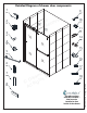
1 Detailed Diagram of shower door components 9 x1 2 x2 3 x2 4 x2 d e e n v i r L e 12 s m e a R e r s D ght 13 © Ri All 10 x1 11 x1 14 x1 x4 15 5 x1 x2 16 x1 7 x4 8 x1 e r n i L e s m e a R e Dr ghts © Ri All d e v 17 x4 18 x4 ©2020 DreamLine.
Parts List Item# DESCRIPTION QTY Item# DESCRIPTION QTY Center Guide Block 1 SafeClose™ Bumper - Left 1 Inside Door Glass 1 Outside Door Glass 1 14 SafeClose™ Bumper - Right 1 2 15 Allen Wrench: 2.5mm / 3mm / 4mm 1 Bulb Vinyl Insert 4 16 ST4.2 x 20 Pan Head Screw 1 08 Bottom Rail 1 17 ST4.
Installation steps 1. Check the threshold for level and the walls for plumb. Measure the finished opening width at the top (at the model height) and bottom. Use these dimensions as “W1” (top) and “W2”(bottom) in Step #2. (Fig 1) d e e n v i r L e s m e a R e r s D ght opening top (W1) _____________ Finished © Ri _____________ All Finished opening bottom (W2) NOTE: This model will only accommodate up to 1/4” for out-of-plumb conditions. W1 ©2020 DreamLine.
2. Cut the Upper Guide Rail (#01) and the Bottom Rail (#08) to fit the finished opening using either a miter saw or a hacksaw and miter box: Upper Guide Rail (#01) ◻ Cut the Upper Guide Rail (#01) to: “W1”(top) dimension - 9/16” (Fig 2a) d e e n v i r L e s m e a R e r s D ght © Ri W1 -9/16” l l A ◻ Cut the Bottom Rail (#08) to: “W2” (bottom) dimension - 5/16” (Fig 2b) Fig 2a Bottom Rail (#08) ©2020 DreamLine.
3. Set the Bottom Rail (#08) onto the threshold, parallel with the outside edge, and mark the position on the threshold. (Fig 3a) ! d e e n v i r L e s m e a R e r s D ght © Ri All NOTE: This model requires a minimum of 3” of flat, level threshold space. 3” m in. Fig 3a 3” m in. d e e in erv L s m e a R e r s D ght approx wall © Ri 3/16” Al2l as spacers to offset the Bottom Rail (#08) from each wall.
4. Apply silicone into the groove along the bottom surface of the Bottom Rail (#08). (Fig 4) d e e n v i r L e s m e a R e r s D ght © Ri All bottom Fig 4 5. Install the Bottom Rail (#08) onto the marked position on the threshold. Apply silicone to the Left and Right SafeClose™ Bumpers (#11 *#14) and install them over the Bottom Rail (#08). (Fig 5) out side 2 d e e in erv L s m e a R e r s D ght © Ri All ©2020 DreamLine.
6. Run a bead of silicone along the inside edge of the Bottom Rail (#08). (Fig 6) ! d e e n v i r L e s m e a R e r s D ght © Ri All Use several strips of Painter’s Tape to hold the Bottom Rail in position while the silicone cures. Fig 6 7. Measure across the width of the threshold to locate and mark the center. The Center Guide Block (#10) must be installed in the center of the threshold. (Fig 7) ©2020 DreamLine.
! This model requires drilling into the threshold for proper installation. Contact the manufacturer of the base or tub with any questions regarding the drilling of holes into their product. 8. Place the Center Guide Block (#10) onto the threshold, over the Bottom Rail (#08) and align the hole with the centerline mark from the previous step. Mark the hole for drilling.
9. Slide the required Bulb Vinyl Inserts (#07) into the Wall Profiles (#06). Position the left Wall Profile (#06) onto the SafeClose™ Bumper (#11) and use a level and hold it plumb. Mark the position of the Wall Profile (#06) and the holes for drilling on the wall. (Fig 9) d e e n v i r L e s m 2 e a R e r s D ght © Ri All 1 3 Fig 9 d e e in erv L s m e a R e r s D ght © i 2 1 R All 10.
11. Apply silicone to the back surface of the Wall Profile (#06). Remove the top of the Guide Rail Bracket Assembly (#02). Place the Wall Profile (#06) back into position on the wall. Remove the top from the Guide Rail Bracket Assembly (#02) and align the Guide Rail Bracket Assembly (#02) with the top two holes in the Wall Profile (#06). Attach the Guide Rail Bracket Assembly (#02) to the wall through the Wall Profile (#06) using the ST4.2 x 40 Countersunk Screws (#17).
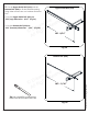
13. Place the Upper Guide Rail (#01) into the installed Guide Rail Bracket Assembly (#02) (on the left in this example), and position the remaining Wall Profile (#19) on the opposite wall, on top of the SafeClose™ Bumper- right (#14). (Fig 13) ! 1 Have an assistant available to help support the upper guide rail during the these steps. d e e n v i r L e s m e a R e r s D ght © Ri All 2 outside ©2020 DreamLine.
14. Hold the Upper Guide Rail (#01) level and the wall profile plumb and mark the position of the bracket on the Wall Profile (#06). (Fig 14) ! If the threshold is out-of-level, the holes in the guide rail bracket will not align with the holes in the wall profile d e e n v i r L e s m e a R e r s D ght © Ri All Fig 14 15. Using the marks from the previous step, drill the holes using a Ø5/16” drill bit and insert the d e e n v i r L e 1m 2 s e a sR e r D ght © Ri All Wall Anchors (#18).
16. Apply silicone to the back surface of the Wall Profile (#06). Place the Wall Profile (#06) back into position on the wall. Remove the top piece from the Guide Rail Bracket Assembly (#02) and align the Guide Rail Bracket Assembly (#02) with the holes in the Wall Profile (#06). Install the Guide Rail Bracket Assembly (#02) to the wall through the Wall Profile (#06) using the ST4.2 x 40 Countersunk Screws (#17).
18. Attach the Wall Profile Caps (#09) to the top of both Wall Profiles (#06). (Fig 18) d e e n v i r L e s m e a R e r s D ght © Ri Fig 18 All 19. Remove the cap and screw from the Roller Assembly (#04) and attach the Roller Assembly (#04) to the Inside Door Glass (#12) and to the Outside Door Glass (#13).
! NOTE: DO NOT install the towel bars on the glass until instructed. DO NOT lift the glass using the towel bars. This could result in damage to the glass and/or serious personal injury. Always use an assistant or a professional grade glass suction cup when handling heavy glass. d e e n v i r L e s m e a R e r s D ght © Ri All 20. From inside the shower, hang the Inside Door Glass (#12) first. Insert one wheel into the notch in the top of the Upper Guide Rail (#01).
. Attach the Roller Guards (#03) to the Outside Door Glass (#13) to prevent the door glass from being lifted off of the Upper Guide Rail (#01). Adjust the Roller Guards (#03) to wihin 1/16” beneath the Upper Guide Rail (#01). (Fig 21a) d e e n v i r L e s m e a R e r s D ght © Ri All de insi roller guard OUTSIDE DOOR INSIDE DOOR ROLLER GUARD ©2020 DreamLine.
! TIP: The wheel assembly bushing that fits through the hole in the glass is elliptical. By rotating this disk, the door glass can be adjusted (tilted) slightly in order to make even contact with the Bulb Vinyl Inserts and prevent leakage.
22. Attach the Towel Bar (#05) to the Inside Door Glass (#12) and to the Outside Door Glass (#13). Be sure to use all of the supplied rubber gaskets to prevent ◾ glass-to-metal contact. (Fig 22) d e e n v i r L e s m e a R e r s D ght © Ri All ! Towel bars are NOT Grab-bars Fig 22 23. Apply a good quality mildew-resistant silicone along the bottom rail and wall profiles where they meet the walls and threshold. (Fig 23) 24 Hours d e e in erv L s m e a R e r s D ght © Ri All ©2020 DreamLine.
Product Maintenance BASES and BACKWALLS: To ensure long-lasting life for your acrylic back walls, wipe them off after each use with a soft cloth. To clean the acrylic back walls use non-abrasive sprays or cream based cleaners. Avoid the use of aerosol spray cleaners. Never use abrasive cleansers, metal brushes or scrapers that could scratch or dull the surface.
d e e in erv L s m e a R e r s t D gh © Ri l l A d e e in erv L s m e a R e r s D ght © Ri l l A TEL: 866-731-2244 FAX: 866-857-3638 DREAMLINE.COM For more information on DreamLine® Shower Doors and Enclosures please visit DreamLine.com ©2020 DreamLine.