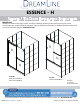
ESSENCE - H SHOWER / TUB DOOR INSTALLATION INSTRUCTIONS IMPORTANT DreamLine® reserves the right to alter, modify or redesign products at any time without prior notice. For the latest up-to-date technical drawings, manuals, warranty information or additional details please refer to your model’s web page on DreamLine.
This model is treated with DreamLine’s exclusive ClearMaxTM Glass technology. This is a specially formulated coating that prevents the buildup of soap and water spots. Install the surface with the ClearMaxTM label towards the inside of the shower. Please note that depending on the model, the glass may be coated on either one or both surfaces. ©2017 DreamLine. All Rights Reserved For best results, squeegee the glass after each use and dry with a soft cloth.
Preparation 1. Prior to installation, examine all boxes and packages for shipping damage and compare the piece count with your packing slip. After opening all boxes and packages read this introduction carefully. Check that all of the needed parts are included in the package by checking off the components on the “Detailed Diagram of Shower Door Components”.
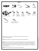
Tools Level Miter saw or Hacksaw Metal File Tape Measure Power Drill Pencil Drill bit (Ø=5/16") (Ø=8mm) Drill bit (Ø=1/8") (Ø=3mm) Phillips Screwdriver Silicone Hammer Painter’s Tape HexHead driver bits 2.5mm, 3mm, 4mm ©2017 DreamLine. All Rights Reserved Tip: Set screw gun clutch to low setting when installing screws and bolts to prevent stripping the heads. Tip: Before installation, cover the shower drain to prevent losing small parts. NOTE: Unpack your unit carefully and inspect it.
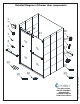
Detailed Diagram of shower door components 1 2 12 13 3 19 20 4 5 21 22 14 23 18 24 ©2017 DreamLine.
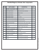
Detailed Diagram of shower door components DESCRIPTION PART NUMBER QTY 01 04184011-1203/04184041-1203/ 04184011-1508/04184041-1508 Upper Guide Rail 1PC 02 07021106/07024106 Guide Rail Bracket Assembly 2Sets 03 07021107/07024107 Roller Guard 2Sets 04 07351022/07354022 Roller 4Sets 05 07221035/07224035/ 07221036/07224036 Towel Bar 2Sets 12 010300001/010300003/010300005 Inside Door Glass 1PC 13 010300002/010300004/010300006 Outside Door Glass 1PC 14 098002/098003/098004 Allen
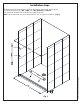
Installation steps 1. Measure the finished opening width at the bottom and at the model height. Use these dimensions as “W1” (top) and “W2”(bottom) in Step #2. Also check the threshold for level and the walls for plumb. Note: This model does not have adjustment for out-of-plumb conditions. (Fig 1) ©2017 DreamLine.
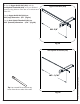
2. Cut the Upper Guide Rail (#01) and the Anti-Splash Threshold (#21) to fit your finished opening using either a miter saw or a hacksaw and miter box: Upper Guide Rail (#01) Cut the Upper Guide Rail (#01) to: “W1”(top) dimension - 5/8” (Fig 2a) Cut the Anti-Splash Threshold (#21) to: “W2” (bottom) dimension - 3/16” (Fig 2b) W1 -5/8” Fig 2a Anti-Splash Threshold (#21) ©2017 DreamLine. All Rights Reserved W2 - 3/16” Tip: Use a metal file to remove any burrs from the cut ends of the rails.
3. Set the Anti-Splash Threshold (#21) onto the threshold and measure in 1/8” from the outside of the threshold evenly across the width. Mark the position of the Anti-Splash Threshold (#21) on the threshold. (Fig 3) NOTE: This model requires a minimum 3-1/4” of flat threshold space for the wall profiles and 2-3/4” of flat threshold space for the center guide block. 3-1 /4” min . 1/8” 2-3 /4” min . Fig 3 1/8” 4.
5. Replace the Anti-Splash Threshold (#21) onto the marked position on the threshold. (Fig 5) TIP: Use a Wall Profile (#19) as a spacer to offset the Anti-Splash Threshold (#21) 1/16” from each wall. The Anti-Splash Threshold (#21) should not make contact with the walls. 1/16” outside wall Wall profile Bottom Rail Fig 5 6. Run a bead of silicone along the Use several strips of Painter’s Tape to hold the bottom rail in position while the silicone cures.
©2017 DreamLine. All Rights Reserved 7. Measure across the width of the threshold to locate and mark the center.
8. Place the Guide Block (#22) onto the threshold, against the Anti-Splash Threshold (#21) and align the hole with the centerline mark from the previous step. Mark the hole for drilling. ◾For installation into a tile threshold, drill a Ø5/16” (8mm) hole and insert the Wall Anchor (#18) ◾For installation into an acrylic threshold, drill an Ø1/8” (3mm) hole and do not use an anchor Apply silicone to the bottom of the Guide Block (#22) and attach it to the threshold using an ST4.2 x 20 Round Head Screw (#24).
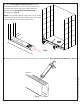
9. Position one of the Wall Profiles (#19) on the wall, over the outside edge of the Anti-Splash Threshold (#21) (see overhead Fig 10). Check for plumb with a level and mark the position of the Wall Profile (#19) and the holes for drilling on the wall. (Fig 10 and Fig 11) inside wall profile wall threshold bottom rail outside ©2017 DreamLine.
10. Using the marks from the previous step, drill the holes using a Ø5/16” drill bit and insert the Wall Anchors (#18). (Fig 12) 1 Ø5/16” 2 ©2017 DreamLine.
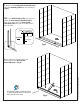
11. Apply silicone to the back surface of the Wall Profile (#19) and place it back in position on the wall. Align the Bumper Guides (#20) with the correct holes and attach them to the wall through the Wall Profile (#19) using the ST4.2 x 40 Round Head Screws (#23). Cover the screw holes with the supplied decorative caps. (Fig 13) decorative cap decorative cap Fig 13 ©2017 DreamLine. All Rights Reserved NOTE: Do Not overtighten the screws as this may deform the wall profile.
12. Remove the top of the Guide Rail Bracket Assembly (#02). Align the Guide Rail Bracket Assembly (#02) with the top two holes in the Wall Profile (#19). Attach the Guide Rail Bracket Assembly (#02) to the wall through the Wall Profile (#19) using the ST4.2 x 40 Countersunk Screws (#16). (Fig 14) 5/16” wall anchors set screw top ST4.2x40 screws (#16) wall bracket Wall Bracket Assembly ©2017 DreamLine. All Rights Reserved NOTE: Do Not overtighten the screws as this may deform the wall profile.
13. Attach the remaining Guide Rail Bracket Assembly (#02) onto the opposite end of the Upper Guide Rail (#01). Place the Upper Guide Rail (#01) into the installed Guide Rail Bracket Assembly (#02), and position the remaining Wall Profile (#19) on the opposite wall. (Fig 15) 1 2 ©2017 DreamLine.
14. Place a level on top of the Upper Guide Rail (#01). When the Upper Guide Rail (#01) is level, mark the position of the Guide Rail Bracket Assembly (#02) on the Wall Profile (#19). (Fig 16) ©2017 DreamLine.
15. Remove the Upper Guide Rail (#01). Remove the Guide Rail Bracket Assembly (#02) from the end of the Upper Guide Rail (#01) and hold it in position on the Wall Profile (#19) at the mark from the previous step. Mark the center of the holes on the wall for drilling through the elongated holes in the wall profile. Also mark the holes on the wall for the two Bumper Guides (#20) through the holes in the Wall Profile (#19). Drill the holes using a Ø5/16” drill bit and insert the Wall Anchors (#18).
17. Install the Guide Rail Bracket Assembly (#02) onto the wall profile and into the wall. (Fig 19) NOTE: Do Not overtighten the screws as this may deform the wall profile. Fig 19 18. Slide the Upper Guide Rail (#01) into both Guide Rail Bracket Assemblies (#02). Install both of the Guide Rail Bracket Assembly (#02) tops and secure with the set screws. (Fig 20) ©2017 DreamLine.
©2017 DreamLine. All Rights Reserved 19. Next, prepare the doors for installation.
20. Remove the cap and screw from the Rollers (#04) and attach the Rollers (#04) to the Inside Door Glass (#12) and to the Outside Door Glass (#13). (Fig 22 and Fig 23) insi de doo r gl ass ou tsi ! de NOTE: DO NOT install the towel bars on the glass until instructed to do so. DO NOT lift the glass using the towel bars. This could result in damage to the glass and/or serious personal injury. Always use an assistant or a professional grade glass suction cup when handling heavy glass.
22. Attach the Roller Guards (#03) to the Outside Door Glass (#13) to prevent the door glass from being lifted off of the Upper Guide Rail (#01). (Fig 24) inside roller guard Fig 24 OUTSIDE DOOR INSIDE DOOR ©2017 DreamLine.
TIP: The wheel assembly bushing that fits through the hole in the glass is elliptical. By rotating this disk, the door glass can be adjusted (tilted) slightly in order to make even contact with both the top and bottom wall bumpers. ◾ Use a shim beneath the door glass to prevent contact with the threshold during adjustments ◾ Temporarily adjust the roller guards for clearance ◾ Remove the cap from the wheel assembly and loosen the bolt ◾ Insert the small 2.
23. Attach the Towel Bars (#05) to the Inside Door Glass (#12) and to the Outside Door Glass (#13). Be sure to use all of the supplied rubber gaskets to protect the glass. (Fig 26) Fig 26 24. Apply a good quality mildew-resistant silicone on the walls and threshold along the bottom profile and wall profiles. (Fig 27) Allow 24 hours for the silicone to fully cure before using the shower. ©2017 DreamLine.
Product Maintenance BASES and BACKWALLS: To ensure long-lasting life for your acrylic back walls, wipe them off after each use with a soft cloth. To clean the acrylic back walls use non-abrasive sprays or cream-based cleaners. Avoid the use of aerosol spray cleaners. Never use abrasive cleansers, metal brushes or scrapers that could scratch or dull the surface. GLASS: To ensure long-lasting life for your glass shower products, wipe them off after each use with a soft cloth.
TEL: 866-731-2244 FAX: 866-857-3638 DREAMLINE.COM For more information on DreamLine® Shower Doors and Enclosures please visit DreamLine.com ©2017 DreamLine.