ENIGMA AIR SHOWER DOOR / TUB DOOR INSTALLATION INSTRUCTIONS IMPORTANT DreamLine® reserves the right to alter, modify or redesign products at any time without prior notice. For the latest up-to-date technical drawings, manuals, warranty information or additional details please refer to your model’s web page on DreamLine.
This model is treated with DreamLine’s exclusive ClearMaxTM Glass technology. This is a specially formulated coating that prevents the buildup of soap and water spots. Install the surface with the ClearMaxTM label towards the inside of the shower. Please note that depending on the model, the glass may be coated on either one or both surfaces. ©2018 DreamLine. All Rights Reserved For best results, squeegee the glass after each use and dry with a soft cloth. ENIGMA AIR manual Ver 1 Rev 5.
Table of Contents Section title Page # Handing Information Installing the Enclosure model 2 3 Troubleshooting and Maintenance Tips 4 Reinforcement Information 5 Preparation Tools 6 7 Detailed Diagram of Shower Door Components 8 Parts List Installation Steps 9 Vinyl Seals 25 SafeStop™ Bumper 26-27 Stoppers 28 Product Maintenance 30 Maintenance Checklist 31 ©2018 DreamLine. All Rights Reserved 10-29 ENIGMA AIR manual Ver 1 Rev 5.
Handing Information PAN EL D OOR Left-Hand door installation DOO R Right-Hand door installation ©2018 DreamLine. All Rights Reserved EL PAN NOTE: This door is reversible for right or left-hand door installation. The right-hand door installation is shown as an example throughout this manual. For the left-hand door installation, simply begin on the opposite wall and reverse the orientation of the steps shown. ENIGMA AIR manual Ver 1 Rev 5.
Installing the Enclosure model NOTE: This manual will describe the installation of the single threshold model of the ENIGMA AIR. For the ENIGMA AIR Enclosure installation, use the installation manual that is packaged with the return panel glass. ENIGMA AIR ENCLOSURE SHOWER ENCLOSURE INSTALLATION INSTRUCTIONS IMPORTANT DreamLine® reserves the right to alter, modify or redesign products at any time without prior notice.
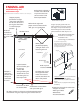
ENIGMA-AIR troubleshooting and maintenance tips Right Hand door installation shown as an example Stopper properly positioned and tight -door stops well before handle can contact the panel glass when door is in the fully open position Guide Rail bracket flush with wall and set screws tight Roller wheels adjusted as needed so that the bulb vinyl seal makes even contact with the wall from top to bottom Rotate disk to adjust Roller wheels tight with proper clearance beneath the door glass and guide block G
Reinforcement for Enigma Series Heavy Glass frameless sliding shower door Install studs OR install 2”x 6” wood blocking between the studs where the Guide Rail Brackets will attach to the wall d Stu or 2” ” X6 2” ” X6 measured from threshold* (see list below) ©2018 DreamLine.
Preparation 1. Prior to installation, examine all boxes and packages for shipping damage and compare the piece count with your packing slip. After opening all boxes and packages read this introduction carefully. Check that all of the needed parts are included in the package by checking off the components on the “Detailed Diagram of Shower Door Components”.
Tools Phillips Screwdriver Painter’s Tape Drill bit (D=5/16") Metal File Pencil Drill bit (D=1/8") Power Drill Professional-grade Glass suction cup Soft Head Hammer Tip: Prior to installation, cover the shower/tub drain with tape to prevent losing screws or small parts. Tip: Set screw gun clutch to low setting when installing screws and bolts to prevent stripping the heads.
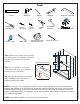
Detailed Diagram of Shower Door Components 7 1 4 8 9 16 5 17 18 6a 6b 6 PAN 2 EL 3 19 DOO R 14 20 15 21 13 12 11 The glass surface with the ClearMax™ label must be installed to face inside of the shower ENIGMA AIR manual Ver 1 Rev 5.2 02/2018 ©2018 DreamLine.
DESCRIPTION QTY 01 U-Channel 1 PC 02 Stationary glass 1 PC 03 Door glass 1 PC 04 Guide Rail 1 PC 05 Stopper 2 PCS 06 Guide Rail Bracket (6a&6b) 2 PCS 07 Glass Bracket 2 PCS 08 Roller 2 PCS 09 Roller Guard 2 PCS 10 Threshold End Cap 1 PC 11 Anti-splash Threshold 1 PC 12 Guide Block 1 PC 13 Anti-water side strip 2 PCS 14 Bumper strip 1 PC 15 Handle 1 PC 16 5/16" plastic wall anchor 7 PCS 17 Countersunk screw ST4.2X40 2 PCS 18 Round head screw ST4.
Installation Steps 1. Check both of the finished walls for plumb and the threshold for level. (Fig 1) NOTE: This model does not allow for out-of-plumb adjustment. NOTE: The right-hand door installation is shown as an example throughout this manual. For the left-hand door installation, simply begin on the opposite wall and reverse the orientation of the steps shown. Fig 1 2. Use a chop saw (or a hacksaw) to cut the stainless steel Guide Rail (#04) from the door end only to fit the finished opening.
! Cut the Guide Rail (#04) from the door end only which is the end opposite from the glass bracket holes. Finished opening (W) - 1” = finished cut length panel end glass bracket holes panel end door end NOTE: Use a metal file to remove any burrs from the cut end of the Guide Rail (#04). Cut from the door end only Metal File Fig 2b ©2018 DreamLine. All Rights Reserved 3. This model requires a minimum 2-1/4” of flat threshold space for installation.
4. Align the outside edge of the U-Channel (#01) with the inside of the mark on the threshold. Use a level to plumb the U-Channel (#01) and mark its position on the wall. Mark the four holes for drilling through the pre-drilled holes in the U-Channel (#01). (Fig 4) U-Channel Fig 4 5. Remove the U-Channel (#01) from the wall and drill the anchor holes using a Ø5/16” drill bit and insert the Wall Anchors (#16).
outside inside 1-1/4" Guide Rail Bracket U-channel H H Right hand door installation shown as example outside outside 1 1/4” Guide Rail Bracket 1 1/4” Fig 6a From the inside of the shower, measure up from the threshold to the mark the bottom of the Guide Rail Bracket (#06) using Table 1 below. While holding the bracket against the edge of the installed U-Channel (#01), mark the wall at the bottom of the bracket to the correct installation height. (Fig 6a and Fig 6b) ©2018 DreamLine.
7. Hold the Guide Rail Bracket (#06) in the marked position and mark the hole for drilling through the Guide Rail Bracket (#06) using a pencil (or center punch). (Fig 7) The guide rail wall bracket should be centered in the bracket as shown to allow for vertical adjustment both up and down. (=) CL (=) top ! Note that the bottom of the bracket is thicker than the top and must be installed correctly bottom Fig 7 8.
9. Insert the Stationary Glass (#02) into the installed U-Channel (#01). (Fig 9) ! Use Caution not to bang the glass into the U-Channel or threshold. Use a Professional-grade Glass suction cup (if available) when handling heavy glass. Fig 9 10. Make sure the Stationary Glass (#02) is parallel to the front edge of the threshold and mark it. Slide the Guide Block (#12) into the notch of the Stationary Glass (#02), and align flush with the edge of the glass.
11. Remove the Stationary Glass (#02) from the U-Channel (#01) and carefully set it aside. (Fig 11) Fig 11 12. To install the Guide Block (#12): Loosen the set screw on the side and remove the guide block face plate (Fig 12.5). Apply silicone to the underside of the Guide Block (#12) and screw the Guide Block (#12) to the threshold as described below: *NOTE: ◾For installation into an Acrylic threshold: ◽drill an Ø1/8”(3mm) hole and use the ST4.
! TIP: Bring the door glass into the shower before permanently installing the stationary panel glass and guide rail because it may be difficult to safely bring the door glass into the shower after the guide rail is installed. pro tec 13. Apply silicone into the U-Channel (#01). tiv ep ad din g DOO Slide the Stationary Glass (#02) firmly into the installed U-Channel (#01). (Fig 13) R Use Caution not to bang the glass into the U-Channel or threshold. ! protective padding Fig 13 14.
15. Align the panel end of the Guide Rail (#04) with the installed Guide Rail Wall Bracket (#6b). Slide the Guide Rail Bracket (#6a) over the Guide Rail Wall Bracket (#6b) and tighten the set screws. (Fig 15) 1 2 Fig 15 ! TIP: Leave the set screws that hold the guide rail to the bracket loose to allow for side-to-side adjustment of the guide rail to make it easier to align the holes in the guide rail with the holes in the panel glass.
17. Level the Guide Rail (#04) across the opening. If necessary, use the set screws on the Guide Rail Bracket (#06) to adjust the level of the Guide Rail (#04) and then fully tighten the Glass Brackets (#07). (Fig 17 and Fig 18) To lower the rail: Loosen the top set screw and tighten the bottom set screw. To raise the rail: Loosen the bottom set screw and tighten the top set screw. Fig 17 18.
19. Remove the Guide Rail (#04) from the Stationary Panel Glass (#02). Remove the Guide Rail Bracket (#06) from the Guide Rail (#04) and hold it back in position on the wall and mark the anchor hole. Drill either a Ø5/16” hole and insert a Wall Anchor (#16), OR when installing to a stud, drill a Ø1/4” hole up to the wood and do not use an anchor. *See notes below. Separate the Guide Rail Bracket (#06) components (Fig 6a and Fig 6b). Attach the Guide Rail Wall Bracket (#06b) to the wall using one ST4.
21. Re-check the Guide Rail (#04) for level and if necessary, adjust with the set screws on the Guide Rail Bracket (#06). (Fig 21) To lower the rail: Loosen the top set screw and tighten the bottom set screw. To raise the rail: Loosen the bottom set screw and tighten the top set screw. ©2018 DreamLine. All Rights Reserved ±0.0 Fig 21 ENIGMA AIR manual Ver 1 Rev 5.
22. Measure the distance from the edge of the Guide Block (#12) to the wall. This distance will be (L). Cut the Anti-Splash Threshold (#11) to the size of: (L). (Fig 22) L L 23. Apply silicone to the bottom of the Anti-Splash Threshold (#11). Remove the face plate from the Guide Block (#12). Insert one end of the Anti-Splash Threshold (#11) into the Guide Block (#12) and replace the guide block face plate. Align the Anti-Splash Threshold (#11) parallel with the front edge of the shower base or threshold.
24. Secure the Anti-Splash Threshold (#11) to the threshold with several pieces of painter’s tape to hold it tight to the threshold until the silicone fully cures. (Fig 24) NOTE: DO NOT install the handle onto the door glass until instructed. DO NOT attempt to lift the glass using the handle. This could result in damage to the glass and/or serious personal injury. Always use an assistant or a professional grade glass suction cup when handling heavy glass. ! Painter’s Tape Fig 24 25.
. Use an assistant or a professional grade glass cup to align the bottom of the Door Glass (#03) with the Guide Block (#12) and hang the door from the Guide Rail (#04). (Fig 26) 1 2 inside 3 Fig 26 ©2018 DreamLine. All Rights Reserved Use a Professional-grade Glass suction cup (if available) when handling heavy glass. Right-hand door installation shown as example ENIGMA AIR manual Ver 1 Rev 5.
. Attach the two Roller Guards (#09) onto the door glass to secure the door to the Upper Guide Rail (#04). Apply Thread Lock Adhesive (#20) to the bolts. Leave no more than a 1/16” gap between the Roller Guards (#09) and the Upper Guide Rail (#04). Tighten the post and screw on the cap. (Fig 27) NOTE: Apply Thread Lock (#20) to the Roller Guard bolt during installation.
29. To install the Bumper (#26) with the 3M tape: Remove the 3M Tape backing and position the Bumper (#26) onto the threshold against the U-Channel (#01) on the stationary panel side of the installation. (Fig 29) ! NOTE: The surfaces need to be clean and free of construction debris before installing the bumper. Wipe the area with an alcohol swab before installation TIP: Install the Bumper (#26) using the 3M tape. Screwing the bumper to the wall using a 5/16” hole and anchor is optional (see step 30).
30. To install the Bumper (#26) with the screw method: Remove the PVC insert and position the Bumper (#26) onto the threshold against the U-Channel on the stationary panel side of the installation and mark the position of the hole on the wall. Drill a Ø5/16” hole and insert the Anchor (#16). Remove the 3M Tape backing and position the Bumper (#26) onto the threshold against the U Channel (#01). Screw to the wall using the ST4.2 x 40 Countersunk screw. Re-insert the PVC insert.
! NOTE: Cover the shower/tub drain with tape prior to removing the set screws to prevent loss. 31. Position the Stoppers (#05), remove the set screws from the Stoppers (#05) and apply Thread Lock Adhesive (#20) to the threads. Reinsert the set screws into the Stoppers (#05). Correctly position the Stoppers (#05) and screw them tightly to the Guide Rail (#04) with the supplied Allen wrench.
32. Apply a good quality mildew-resistant silicone along the connection of the stationary glass with the walls and the threshold. (Fig 32) ! Allow 24 hours for the silicone to fully cure before using the shower. ©2018 DreamLine. All Rights Reserved 24 Hours Fig 32 ENIGMA AIR manual Ver 1 Rev 5.
Product Maintenance BASES and BACKWALLS: To ensure long-lasting life for your acrylic back walls, wipe them off after each use with a soft cloth. To clean the acrylic back walls use non-abrasive sprays or cream-based cleaners. Avoid the use of aerosol spray cleaners. Never use abrasive cleansers, metal brushes or scrapers that could scratch or dull the surface. GLASS: To ensure long-lasting life for your glass shower products, wipe them off after each use with a soft cloth.
Enigma-Air Maintenance checklist ©2018 DreamLine.
TEL: 866-731-2244 FAX: 866-857-3638 DREAMLINE.COM For more information on DreamLine® Shower Doors and Enclosures please visit DreamLine.com ©2018 DreamLine.