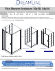
Flex Shower Enclosure 30x30, 34x34 SHOWER ENCLOSURE INSTALLATION INSTRUCTIONS IMPORTANT DreamLine® reserves the right to alter, modify or redesign products at any time without prior notice. For the latest up-to-date technical drawings, manuals, warranty information or additional details please refer to your model’s web page on DreamLine.
FLEX ENCLOSURE SHOWER ENCLOSURE INSTALLATION INSTRUCTIONS IMPORTANT DreamLine® reserves the right to alter, modify or redesign products at any time without prior notice. For the latest up-to-date technical drawings, manuals, warranty information or additional details please refer to your model’s web page on DreamLine.
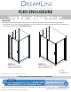
Wall profile Return panel Wall profile Expandable rail Return panel glass Stationary panel glass Corner profile Door Glass Wall profile* do or ( *not used with corner profile) ur ret l ne a np Expandable rail USE THE INSTALLATION MANUAL THAT IS PACKAGED WITH THE FLEX DOOR TO ASSEMBLE AND INSTALL THE DOOR SECTION. ! USE THIS MANUAL TO ASSEMBLE AND INSTALL THE RETURN PANEL AND FOR THE ENCLOSURE DIMENSIONS NOTE: This model is reversible for left or right-hand installation.
Table of Contents Section title Page # Shower Enclosure Diagram Preparation Tools 4 Diagram of Shower enclosure components Parts List 8 9 Installation Steps 10-18 Vinyl Seals 17 Product maintenance 19 5 ©2018 DreamLine.
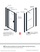
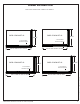
Shower Enclosure Plan RIGHT-HAND RETURN PANEL SHOWN AS AN EXAMPLE SHDR-2230300-RT-01 30-1/2” 32-1/2” min to 36-1/2” max 28-1/2 “min to 32-1/2” max 1-1/2” minimum threshold required 34-1/2" SHDR-2234580-RT-01 34-1/2" 1-1/2” minimum threshold required 56-1/2” min to 60-1/2” max ©2018 DreamLine.
This shower enclosure requires a minimum 1-1/2” wide threshold for installation. Compare the overall outside dimensions of the shower enclosure model size as shown on the “Shower Enclosure Plan” with the finished threshold to ensure proper fit prior to beginning installation. -1/ 32 2 “m -1/ in 44 2” m to 32 -1/ in -1 56 2” m to 36 /2” m -1/ i -1/ ax 2” n to 48 2” m mi nt a o 6 1/2” x 0-1 max /2” ma x 1-1/2” minimum threshold required 2” -1/ 2” 0 3 -1/ 34 ©2018 DreamLine.
Preparation 1. Prior to installation, examine all boxes and packages for shipping damage and compare the piece count with the packing slip. After opening all boxes and packages read this introduction carefully. Check that all of the necessary parts are included in the package by checking off the components on the “Detailed Diagram of Shower Door Components”.
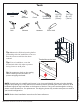
Tools Level Power Drill Tape Measure Pencil Silicone Drill bit Ø5/16" (8mm) Phillips Screwdriver Drill bit Ø=1/8" (3mm) Razor Knife Hammer Top Middle Tip: Measure the finished opening before proceeding with the installation to be sure that the correct model size has been ordered. Bottom Threshold must be level. W Tip: Prior to installation, cover the shower/tub drain with tape to prevent losing screws or small parts. ! ©2018 DreamLine.
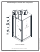
Detailed Diagram of shower door components 10 1 3 11 2 4 5 9 6 Doo r 7 13 tur Re l ne a np ©2018 DreamLine.
Parts List Door packing List 01 02 03 04 05 Wall profile* Door assembly Wall anchor Pan head screw ST4.2×10 Truss head screws ST4.2×40 2pcs* 1set 8pcs 10pcs 8pcs 06 07 08 13 Decorative cover Flanged anti-water strip Bottom anti-water strip Handle 10pcs 1pc 1pc 1pc * Only one Wall Profile is used with the shower enclosure installation Return panel packing List 6pcs 3pcs 1pc 10 11 Corner profile Return panel wall pofile 1pc 1pc ©2018 DreamLine. All Rights Reserved 04 Round head screw ST4.
Installation steps 1. The width of the shower enclosure model is adjustable and can be adjusted to the size of your shower base or custom threshold. Mark the position of the Wall profile (#01) and the Return Panel Wall Profile (#11) on the wall according to the model size and dimensions provided in the size table below. Wall Profile Return Profile Place the Wall Profile (#01) and the Return Panel Wall Profile (#11) onto the threshold against the finished wall. Use a level to adjust to plumb.
2. Mark the holes on the wall for drilling through the pre-drilled holes in the Wall Profile (#01). Drill the holes into the wall using a Ø 5/16 drill bit and insert the Wall Anchors (#03). 3 2 1 Ø 5/16" 4 6 5 Apply silicone to the back surface of the Wall Profile (#01 ) and place it back in position on the wall. Attach the Wall profile (#01) to the wall with the Truss head screws ST4.2×40 (#05). (Fig 2) 3.
USE THE INSTALLATION MANUAL PACKAGED WITH THE FLEX DOOR TO ASSEMBLE AND INSTALL THE DOOR SECTION. (Fig 4) 28” and 32” model 42”, 48” and 60” model Pre-assembled Assembly required 4. Move the Door assembly onto the threshold ©2018 DreamLine. All Rights Reserved and slide the Stationary glass profile into the Wall profile (#01).
5. Slide the Corner profile (#10) over the aluminum edge of the Return Panel Assembly (#09). Drill Ø 1/8” holes through the predrilled holes on the Corner profile (#10) into the aluminum profile on the Return Panel Assembly (#09). Secure the Corner profile (#10) to the Return Panel Assembly (#09) with the Pan head screws ST4.2×10 (#04). (Fig 5) 1 e insid 2 Ø 1/8" ide outs 3 Fig 5 ©2018 DreamLine. All Rights Reserved 6.
7. Extend the width of the Door assembly (#02) by sliding the top and bottom expanding rails toward the Corner profile (#10). Insert the Door Glass side into the Corner profile (#10). (Fig7) NOTE: The maximum adjustment of the Expanding rails is 3”. Do not expand the rails more than 3”. 1 2 3 4 Fig 7 8. Make sure the Door assembly (#02) is fully extended into the Wall profile (#01) and the Corner Profile (#10). Adjust top and bottom Expanding rails to the same length, making the door area square.
9. From inside of the shower, drill holes into the top and bottom Expanding rails through the predrilled holes using an Ø 1/8” drill bit. ATTENTION: Drill only through the first layer of the Expanding rail. Secure the Expanding rails using Pan head screws ST4.2×10 (#04) with the raised white washers. Cover exposed screw heads with Decorative covers (#06). (Fig 9) 1 Ø 1/8” 2 3 5 6 ins ide ins ide Ø 1/8” 4 ©2018 DreamLine.
10. Perform the final adjustments to the Door assembly (#02) and Return panel glass (#09) as necessary. Operate the Door Glass to make sure that the magnetic strips are aligned and make full contact from top to bottom. Drill holes into the aluminum profile of the Door assembly through the predrilled holes in the Wall profile (#01) using an Ø 1/8” drill bit. Drill Ø 1/8” holes into the aluminum profile through the predrilled holes in the Return panel wall profile (#11).
11. Drill holes into the aluminum profile of the Door assembly (#02) through the predrilled holes in the Corner Profile (#10) using an Ø 1/8 drill bit. Secure the Door assembly inside the Corner Profile (#10) using the Pan Head Screws ST4.2×10 (#04) with the raised white washers. Cover the exposed screw heads with the Decorative Covers (#06). (Fig 11) 1 3 2 Ø 1/8” anel np etur r do or ins ide Fig 11 RIGHT-HAND RETURN PANEL SHOWN AS AN EXAMPLE 12.
13. Apply a good quality mildew-resistant silicone along the interior perimeter where the profiles meet the walls and threshold. (Fig 13) ! Allow 24 hours for the silicone to cure before using the shower. ©2018 DreamLine.
Product Maintenance BASES and BACKWALLS: To ensure long-lasting life for your acrylic back walls, wipe them off after each use with a soft cloth. To clean the acrylic back walls use non-abrasive sprays or cream based cleaners. Avoid the use of aerosol spray cleaners. Never use abrasive cleansers, metal brushes or scrapers that could scratch or dull the surface. GLASS: To ensure long-lasting life for your glass shower products, wipe them off after each use with a soft cloth.
For more information on DreamLine® Shower Doors and Enclosures please visit DreamLine.com ©2018 DreamLine. All Rights Reserved TEL: 866-731-2244 FAX: 866-857-3638 DREAMLINE.
FLEX 28”x 72” / 32” x 72” SHOWER DOOR INSTALLATION INSTRUCTIONS IMPORTANT DreamLine® reserves the right to alter, modify or redesign products at any time without prior notice. For the latest up-to-date technical drawings, manuals, warranty information or any other details, please refer to your model’s web page on DreamLine.com Model#s: SHDR-22287200-01 SHDR-22327200-01 Finish -01 = Chrome Right hand door installation shown ® For more information about DreamLine products please visit DreamLine.
NOTE: This manual will describe the installation of the single threshold model of the FLEX Shower Door. For the FLEX Shower Enclosure installation, please also use the manual that is packaged with the return panel glass. FLEX Shower Door Manual Ver 2 Rev 8 01/2018 © 2018 DreamLine.
Preparation 1. Prior to installation, examine all boxes and packages for shipping damage and compare the piece count with your packing slip. After opening all boxes and packages read this introduction carefully. Check that all of the needed parts are included in the package by checking off the components on the “Detailed Diagram of Shower Door Components”.
Tools Required FLEX Shower Door Manual Ver 2 Rev 8 01/2018 © 2018 DreamLine.
Detailed Diagram of Shower Door Components Part List 01 02 03 04 05 Wall profile Door assembly Wall anchor Round head screws ST4.2×10 Truss head screws ST4.2×40 2pcs 1set 8pcs 10pcs 8pcs 06 07 08 13 Decorative cap and washer Flanged anti-water strip Bottom anti-water strip Handle 10pcs 1pc 1pc 1pc NOTE: Unpack your unit carefully and inspect it. Lay it out and identify all parts using the detailed diagram and packing list in this manual as a reference.
Door Assembly Diagram Alluminum profile Stationary glass Expandable rail Glass door Alluminum profile Expandable rail FLEX Shower Door Manual Ver 2 Rev 8 01/2018 © 2018 DreamLine.
Shower Door Installation 1. Prior to the Shower door installation, the installation of the shower base and plumbing must be completed. See Fig. 1 for details. W Fig. 1 2. Slide the Wall profiles (01) over the Door assembly (02) on both sides. Be sure that the flanges on the Wall Profiles (01) face in towards the shower. See Fig. 2 & Fig. 3 for details. Fig. 2 FLEX Shower Door Manual Ver 2 Rev 8 01/2018 © 2018 DreamLine.
NOTE: Flip the entire assembly for opposite installation. Fig. 3 3. Move the Door assembly (02) with the Wall profiles (01) onto the Shower base with the Stationary glass side tight to the wall. Adjust the Door assembly (02) by stretching the top and bottom Expanding rails evenly to extend the Door assembly (02) tight to the opposite wall.
4. Adjust the Door assembly (02) so that it is plumb by checking with a level. See Fig. 5 for details. Fig. 5 5. Have an assistant hold the Door assembly (02) in the correct position and mark the walls through the pre-drilled holes in the flange of the Wall Profiles (01). 1 See Fig. 6 for details. Inside 2 Outside Inside Fig. 6 FLEX Shower Door Manual Ver 2 Rev 8 01/2018 © 2018 DreamLine.
6. Set the Door assembly (02) aside; drill the holes using a Ø5/16” drill bit and insert the Wall anchors (03). 1 Ø 5/16” See Fig. 7 for details. 2 Fig. 7 1 7. Apply silicone along the Wall Profiles (01) and around the holes on the wall. Place the Wall Profiles (01) back on the Shower base into the correct position and secure them to the walls using the Truss head screws ST4.2×40 (05). See Fig. 8 and Fig. 9 for details. 2 3 Fig. 8 FLEX Shower Door Manual Ver 2 Rev 8 01/2018 © 2018 DreamLine.
1 2 3 NOTE: If the finished opening width is at the minimum for the model size, attach one wall profile to the wall, set the door assembly back into position on the threshold into the installed wall profile and then attach the remaining wall profile to the wall. Fig. 9 8. Place the Door assembly (02) back onto the threshold. See Fig. 10 for details. Fig. 10 FLEX Shower Door Manual Ver 2 Rev 8 01/2018 © 2018 DreamLine.
9. Install the Handle (13) onto the Door assembly (02). Insert the Door assembly (02) with the Stationary glass side into the Wall profile (01). 1 See Fig. 11 for details. Note: Do Not lift the unit using the handle as this could result in damage to the glass and/or serious personal injury. 2 Fig. 10 Fig. 11 10. Extend the Door assembly (02) toward the opposite wall and insert the Glass door side into the Wall profile (01). See Fig. 12 and Fig. 13 for details. Fig.
Fig. 13 11. Make sure the Door assembly (02) is fully extended into the Wall profiles (01). Adjust the top and bottom Expanding rails to the same length so that the door opening is square. Use a tape measure for accuracy. See Fig. 14 for details. Fig. 14 FLEX Shower Door Manual Ver 2 Rev 8 01/2018 © 2018 DreamLine.
1 12. Drill holes into the top and bottom Expanding rails through the predrilled holes using an Ø 1/8” drill bit. 4 Ø 1/8" inside ATTENTION: Do not drill all the way through the Expanding rail, only through the first layer. Secure the Expanding rails using the Round head screws ST4.2×10 (04) and the raised white washers. Cover the exposed screw heads and washers with the Decorative caps (06). inside 2 ATTENTION: Do not drill all the way through the Expanding rail, only through the first layer.
14. Attach the Flanged Anti-water strip (07) to the vertical edge of the Stationary glass. Open the door and attach the Bottom Anti-water strip (08) to the bottom of the door glass from the pivot to the edge of the magnetic strike rail and trim off the excess. Next, attach the cut off to the bottom of the door glass, opposite of the pivot and trim to fit. Attach both pieces of the Bottom Anti-water strip (08) to the bottom edge of the Glass door. outside See Fig. 17 for details.
Product Maintenance BASES and BACKWALLS: To ensure long lasting life for your acrylic back walls: wipe them off after each use with a soft cloth. To clean the acrylic back walls use non-abrasive sprays or cream based cleaners. Avoid the use of aerosol spray cleaners. Never use abrasive cleansers, metal brushes or scrapers that could scratch or dull the surface. GLASS: To ensure long lasting life for your glass shower products: wipe them off after each use with a soft cloth.
TEL: 866-731-2244 FAX: 866-857-3638 DREAMLINE.COM For more information on DreamLine® Shower Doors and Enclosures please visit DreamLine.