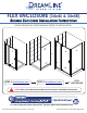
FLEX ENCLOSURE (34x46 & 34x58) SHOWER ENCLOSURE INSTALLATION INSTRUCTIONS PLEASE REVIEW THIS ENTIRE MANUAL PRIOR TO INSTALLATION + STEP 1: Install Shower Door ! = STEP 2: Install Return Panel FLEX ENCLOSURE NOTE: Refer to the Return Panel Manual for Enclosure Installation dimensions. For more information about DreamLine® products please visit DreamLine.
FLEX 42x72“/ 48x72“/ 54x72”/ 60x72” / 60x58” d SHOWER DOOR INSTALLATION INSTRUCTIONS e ne v i r L e s m e a R e Dr ghts © Ri l l A IMPORTANT DreamLine® reserves the right to alter, modify or redesign products at any time without prior notice. For the latest up-to-date technical drawings, manuals, warranty information or additional details please refer to your model’s web page on DreamLine.
Table of Contents Page # Section title Preparation Tools d e e n v i r L e s m e a R e r s D ght © Ri All Parts Diagram of Shower Door Components Parts List Model Overview Installation Steps Vinyl Seals Product Maintenance 2 3 4 5 6 7-19 16-17 20 ! If you have purchased the FLEX Shower Enclosure model: Refer to the “Shower Enclosure Plan” in the manual that is packaged with the return panel glass for the proper dimension to install the door based on the enclosure size.
Preparation 1. Prior to installation, examine all boxes and packages for shipping damage and compare the piece count with your packing slip. After opening all boxes and packages read this introduction carefully. Check that all of the needed parts are included in the package by checking off the components on the “Detailed Diagram of Shower Door Components”.
Tools Level Drill bit (Ø=5/16") (8mm) d e e n v i r L e s m e a R e r s D ght © Ri All Tape Measure Drill bit (Ø=1/8") (3mm) Phillips Screwdriver Pencil Power Drill Hammer Tip: Measure the finished opening before Razor Knife 100% Silicone Top proceeding with the installation to be sure that the correct model size has been ordered. d e e n v i r L e s m e a R e r s D ght © Ri ! W l l A Threshold must be level.
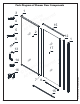
Parts Diagram of Shower Door Components 4 5 1 d e e n v i r L e s m e a R e r s D ght 15 © Ri All 2 12 6 17 13 14 16 1 d e e n v i r L e s m e a R e r s D ght © Ri All 7 ©2020 DreamLine.
Parts List Part# DESCRIPTION 1 Wall profile 2 QTY Part# DESCRIPTION d e v QTY 2pcs 12 Magnetic Strike Profile 1pc Panel Glass assembly 1set 13 Handle 1pc 3 Wall anchor 8pcs 14 ST4.2×25 Round head screw 4pcs 4 ST4.2×10 Round head screw 10pcs 15 Top & Bottom pivot Rail 2pcs 5 ST4.
Model Overview Alluminum wall profile d e e n Stationary panel v i glass assembly r L e s m e a R e r Expandable s D ght rail © Ri Door Glass All pa ne l Alluminum wall profile do or ©2020 DreamLine.
Installation steps 1. Insert the Top & Bottom Pivot Rails (#15) into the expandable rails of the Stationary panel Assembly (#02).
2. Attach the Magnetic Strike Profile (#12) to the Top & Bottom Pivot Rails (#15) using four of the ST4.2 x 25 Round Head Screws (#14). (Fig 2) d e e n v i r L e s m e a R e r s D ght © Ri All ins ide inside Fig 2 d e e n v i r L e s m e a R e r s D ! ght © Ri All FLEX 42x72 48x72 54x72 60x72 60x58 Shower and Tub Door manual Ver 1 Rev 4 072019 ©2020 DreamLine. All Rights Reserved TIP: Apply some wax or dish soap to the screws to make assembly easier and to prevent stripping the screws.
3. Slide both of the Wall Profiles (#01) over the frame assembly. Be sure that the flanges on the Wall Profiles (#01) face in towards the shower. (Fig 3) d e e n v i r L e s panel m e a R e r s D ght © Ri All inside inside inside bottom for either left or right hand door installation. However, the flanges on the wall profiles must face into the shower. (Fig 4) Fig 3 d e e n v i r L e s m e a R e r s D ght © nel Ri pa ne l pa ll A or do a are ©2020 DreamLine. All Rights Reserved 4.
5. Check the threshold of the finished opening to make sure that it is level. (This model does not allow for out-of-level adjustment) (Fig 5) d e e n v i r L e s m e a R e r s D ght © Ri All 6. Place the assembly onto the threshold at the desired location and extend the expandable Top & Bottom Pivot Rails (#15) evenly. (Fig 6) Fig 5 1 d e e n v i r L e s m e a R e r s D ght © Ri All FLEX 42x72 48x72 54x72 60x72 60x58 Shower and Tub Door manual Ver 1 Rev 4 072019 ©2020 DreamLine.
7. The opening for the door glass must be square. Measure the top and bottom of the door opening and adjust the Expandable Rails as necessary. Push the Wall Profiles (#01) tight to the walls to compensate for up to 1/2” out-of-plumb per wall. (Fig 7) ! d e e n v i r L e s m e a R e r s D ght © Ri All Make sure that the Wall Profiles (#01) are tight to the threshold and even with the top of the frame assembly. the d mus oor ope t be n squa ing re Fig 7 8.
9. Move the frame assembly aside and remove the Wall Profiles (#01). Drill the holes into the walls using a Ø5/16” (8mm) drill bit and insert the Wall Anchors (#03). (Fig 9) 1 Ø5/16” (8mm) d e e n v i r L e s m e a R e r s 3 D ght © Ri All Ø5/16” (8mm) 2 4 Fig 9 10. Apply a bead of silicone to the back of the Wall Profiles (#01) and the screw holes where the Wall Profiles (#01) will be installed. Attach the Wall Profiles (#01) to the wall using the ST4.2 x 40 Truss Head Screws (#05).
11. Place the assembly back onto the threshold and into the panel-side Wall Profile (#01) first. (Fig 11) d e e n v i r L e s m e a R e r s D ght © Ri All Fig 11 12. Extend the Expandable Rails evenly so that the Magnetic Strike Profile (#12) goes into the opposite Wall Profile (#01) on the door-side of the opening. (Fig 12) 1 ©2020 DreamLine.
13. Check and adjust the door opening for square and make certain that the entire assembly is tight to the threshold. (Fig 13) d e e n v i r L e s m e a R e r s D ght © Ri All the d mus oor ope t be n squa ing re Fig 13 14. Install the Top & Bottom Pivot Hardware (#16) into the pivot bushings in the Top & Bottom Pivot Rails (#15). (Fig 14) pivot rotation ©2020 DreamLine.
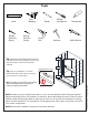
! NOTE: DO NOT install the handle onto the door glass until instructed. DO NOT attempt to lift the glass using the handle. This could result in damage to the glass and/or serious personal injury. Always use an assistant or a professional grade glass suction cup when handling heavy glass. d e e n v i r L e s m e a R e r s D ght © Ri All ! Note: 15. Carefully install the Door Glass (#17) onto the Top & Bottom Pivot Hardware (#16). Make certain that all gaskets are in place to protect the glass.
16. Trim the Bottom Sweep vinyl (#08) to fit on both sides of the bottom pivot and attach both pieces to the bottom of the Door Glass (#17) (Fig 16) d e e n v i r L e s m e a R e r s D ght © Ri All ! NOTE: Measure to the edge of the door and notch the Bottom Sweep vinyl (#08) with a razor knife to fit around the magnet strip, leaving the bottom deflector intact. Fig 16 do or d e e n v i r L e s m e a R e r s D ght © Ri do or All (Fig 17) ©2020 DreamLine. All Rights Reserved 17.
18. Attach the Vinyl Seal with Flexible Fin (#07) to the vertical edge of the Stationary Panel Glass (#02) with the flange facing into the shower. (Fig 18) d e e n v i r L e s m e a R e r s D ght © Ri All inside pa ne l outside pa inside ne l ©2020 DreamLine.
1 19a. Once all adjustments have been made, drill pilot holes from inside of the shower into the Top & Bottom Pivot Rails (#15) through the predrilled holes using an Ø1/8” drill bit. ! Ø1/8” (3mm) d e e n v i r L e s 3 m e a R e r s D ght © Ri All 2 ins ins ide ide NOTE: Do Not drill the rails throughout, only through the first layer. Ø1/8” (3mm) ST4.2x10 & washer 19b. Secure the Expanding rails using the Round Head Screws ST4.2×10 (#04) and the raised white washers.
. Apply a good quality mildew-resitant silicone around the interior perimeter along both walls and the threshold. (Fig 21) ! The surfaces need to be clean and free of debris before applying silicone. Allow 24 hours for the silicone to cure before using the shower. d e e n v i r L e s m e a R e r s D ght © Ri All 24 Hours ©2020 DreamLine.
Product Maintenance BASES and BACKWALLS: To ensure long-lasting life for your acrylic back walls, wipe them off after each use with a soft cloth. To clean the acrylic back walls use non-abrasive sprays or cream based cleaners. Avoid the use of aerosol spray cleaners. Never use abrasive cleansers, metal brushes or scrapers that could scratch or dull the surface.
d e e n v i r L e s m e a R e r s D ght © Ri All d e e n v i r L e s m e a R e r s D ght © Ri All TEL: 866-731-2244 FAX: 866-857-3638 DREAMLINE.COM For more information on DreamLine® Shower Doors and Enclosures please visit DreamLine.com ©2020 DreamLine.
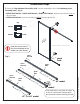
d e e in erv L s m e a R e FLEX ENCLOSURE r s t DNCLOSURE SHOWER E © Righ INSTALLATION INSTRUCTIONS PLEASE REVIEW All THIS ENTIRE MANUAL PRIOR TO INSTALLATION d e e in erv L s m e a R e r s t D gh MODEL #s © i R MODEL #s l l A SHDR-2230300-RT-## SHDR-2234340-RT-## Right-hand return panel installation shown SHDR-2234420-RT-## SHDR-2240420-RT-## SHDR-2234460-RT-## SHDR-2234540-RT-## SHDR-2234580-RT-## ##=finish 01- Chrome 04 - Brushed Nickel IMPORTANT! DreamLine® reserves the right to alter, modify or re
NOTE This manual will describe the installation steps for the Return panel only and contains dimensions for the proper location to install the door section based on the enclosure model size. The installation manual for the door section of this enclosure is packaged with the door glass.
Table of Contents Page # Shower Enclosure Plan Preparation Tools e r n i L e s m e a R e Dr ghts © Ri All Detailed Diagram of Shower Enclosure Components Parts List Installation Steps Vinyl Seals Product maintenance d e v d e e in erv L s m e a R e r s D ght © Ri All ! This product should be installed by someone familiar with the construction requirements for this type of product and the care necessary for the safe installation and operation of the product.
Shower Enclosure Plan RIGHT-HAND RETURN PANEL SHOWN AS AN EXAMPLE d e e n v i r L e s m e a R e r s D ght © Ri All SHDR-2230300-RT-01/04 30-1/2” SHDR-2234340-RT-01/04 1-1/2” minimum threshold required 1-1/2” minimum threshold required 28-7/16 “min to 32-7/16” max 32-7/16” min to 36-7/16” max SHDR-2234460-RT-01/04 34-1/2" SHDR-22547200-RT-01/04 1-1/2” minimum threshold required 34-1/2" 34-1/2" 1-1/2” minimum threshold required d e e n v i r L e s m e a R e r s D ght © Ri All 44-7/16” min to
Shower Enclosure Plan (Cont’d.) This shower enclosure requires a minimum 1-1/2” wide threshold for installation. Compare the overall outside dimensions of the shower enclosure model size as shown on the “Shower Enclosure Plan” with the finished threshold to ensure proper fit prior to beginning installation.
Preparation 1. Prior to installation, examine all boxes and packages for shipping damage and compare the piece count with the packing slip. After opening all boxes and packages read this introduction carefully. Check that all of the necessary parts are included in the package by checking off the components on the “Detailed Diagram of Shower Door Components”.
Tools Level Power Drill Drill bit d e e Ø5/16" in erv(8mm) L s m e a R e r s D ght © Ri All Tape Measure Phillips Screwdriver Pencil Silicone Hammer Drill bit Ø=1/8" (3mm) Razor Knife Top Middle Tip: Measure the finished opening before proceeding with the installation to be sure that the correct model size has been ordered. (see the Shower Enclosure Plan on page 3) Bottom Threshold must be level.
Detailed Diagram of Shower Enclosure Components d e e n v 11 i r L e 10 1 s m e a R e r s D ght © Ri All 3 2 4 5 6 9 Doo r 7 13 tur Re l ne a np d e e n v i r L e s m e a R e r s D ght © Ri All ©2020 DreamLine.
Parts List Door packing List 01 02 03 04 05 d e v e r n i L e s m e a R e Dr ghts © Ri Return panel packing List l l A Wall profile* Door assembly Wall anchor ST4.0 x 10 Pan head screw ST4.2 x 40 Truss head screws 2pcs* 1set 8pcs 10pcs 8pcs 06 07 08 13 Decorative cover Vinyl Seal with Flexible Fin Bottom Sweep vinyl Handle 10 1pc 1pc 1pc * Only one Wall Profile is used with the shower enclosure installation 04 ST4.
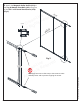
Installation steps 1. The overall width of the shower enclosure model is adjustable and can be adjusted to the sizes listed in Table A (under W2) Mark the position of the Wall profile (#01) and the Return Panel Wall Profile (#11) on the walls according to the model size and dimensions provided in Table A below. d e e n v i r L e s m e a R e r s D ght © Ri All Wall Profile Return Profile Place the Wall Profile (#01) and the Return Panel Wall Profile (#11) onto the threshold against the finished wall.
2. Mark the holes on the wall for drilling through the pre-drilled holes in the Wall Profile (#01). 3 2 1 d e e n i 4 erv 5 L s m e a R e r s D ght © Ri All Ø 5/16" Drill the holes into the wall using a Ø 5/16 drill bit and insert the Wall Anchors (#03). 6 Apply silicone to the back surface of the Wall Profile (#01 ) and place it back in position on the wall. Attach the Wall profile (#01) to the wall with the ST4.2 x 40 Truss head screws(#05). (Fig 2) 3.
USE THE INSTALLATION MANUAL PACKAGED WITH THE FLEX DOOR TO ASSEMBLE AND INSTALL THE DOOR SECTION. (Fig 4) d e e in erv L s m e a R e r s D ght © Ri All 28” and 32” model 42”, 48”, 54“ and 60” model Pre-assembled Assembly required 4. Move the Door assembly onto the threshold and slide the Stationary glass profile into the Wall profile (#01). (Fig 4) ©2020 DreamLine.
5. Slide the Corner profile (#10) over the vertical rail on the Return Panel Assembly (#09). Drill Ø 1/8” holes through the predrilled holes on the Corner profile (#10) into the aluminum profile on the Return Panel Assembly (#09). d e e n v i r L e s m e a R e r s D ght © Ri All Secure the Corner profile (#10) to the Return Panel Assembly (#09) with the ST4.0 x 10 Pan head screw (#04). (Fig 5) Ø 1/8” bit Inside of return panel Fig 5 d e e n v i r L e s m e a R e r s D ght © Ri All ©2020 DreamLine.
7. Extend the width of the Door assembly (#02) by sliding the top and bottom expanding rails toward the Corner profile (#10). Insert the Door Glass side into the Corner profile (#10). (Fig7) d e e n v i r L e s m e a R 2 re s D ght © Ri All NOTE: The maximum adjustment of the Expanding rails is 3”. Do not expand the rails more than 3”. 1 3” Max. 3 4 3” Max. Fig 7 8. Make sure the Door assembly (#02) is fully extended into the Wall profile (#01) and the Corner Profile (#10).
9. From inside the shower, drill holes into the top and bottom Expanding rails through the predrilled holes using an Ø 1/8” drill bit. ATTENTION: Drill only through the first layer of the Expanding rail. d e e in erv L s m e a R e r s D ght © Ri All Secure the Expanding rails using ST4.0 x 10 Pan head screw (#04) with the raised white washers. Cover exposed screw heads with Decorative covers (#06).
10. Perform the final adjustments to the Door assembly (#02) and Return panel glass (#09) as necessary. Operate the Door Glass to make sure that the magnetic strips are aligned and make full contact from top to bottom. Drill holes into the aluminum profile of the Door assembly through the predrilled holes in the Wall profile (#01) using an Ø 1/8” drill bit. Drill Ø 1/8” holes into the aluminum profile through the predrilled holes in the Return panel wall profile (#11).
11. Drill holes into the aluminum profile of the Door assembly (#02) through the predrilled holes in the Corner Profile (#10) using an Ø 1/8 drill bit. Secure the Door assembly inside the Corner Profile (#10) using the ST4.0 x 10 Pan head screw (#04) with the raised white washers. Cover the exposed screw heads with the Decorative Covers (#06).
13. Apply a good quality mildew-resistant silicone along the interior perimeter where the profiles meet the walls and threshold. (Fig 13) ! The surfaces need to be clean and free of debris before applying silicone. Allow 24 hours for the silicone to cure before using the shower. d e e in erv L s m e a R e r s D ght © Ri All 24 Hours ©2020 DreamLine.
Product Maintenance BASES and BACKWALLS: To ensure long-lasting life for your acrylic back walls, wipe them off after each use with a soft cloth. To clean the acrylic back walls use non-abrasive sprays or cream based cleaners. Avoid the use of aerosol spray cleaners. Never use abrasive cleansers, metal brushes or scrapers that could scratch or dull the surface.
d e e in erv L s m e a R e r s D ght © Ri All TEL: 866-731-2244 FAX: 866-857-3638 DREAMLINE.COM For more information on DreamLine® Shower Doors and Enclosures please visit DreamLine.com ©2020 DreamLine.