ENIGMA-XO ENCLOSURE SHOWER ENCLOSURE INSTALLATION INSTRUCTIONS IMPORTANT DreamLine® reserves the right to alter, modify or redesign products at any time without prior notice. For the latest up-to-date technical drawings, manuals, warranty information or additional details please refer to your model’s web page on DreamLine.
This model is treated with DreamLine’s exclusive ClearMaxTM Glass technology. This is a specially formulated coating that prevents the buildup of soap and water spots. Install the surface with the ClearMaxTM label towards the inside of the shower. Please note that depending on the model, the glass may be coated on either one or both surfaces. For best results, squeegee the glass after each use and dry with a soft cloth. ENIGMA-XO Shower Enclosure manual Ver 1 Rev 1 01/2018 ©2018 DreamLine.
Table of Contents Section title Important Information Regarding the Installation of this Door Page # 2 Reinforcement for Enigma Series Heavy Glass Frameless Door 3 Preparation 4 Tools Detailed Diagram of Shower Door Components 5 6, 7 Enclosure Plan (measurements) 8, 9 Installation Steps 10-31 Vinyl Seals 27 Roller Adjustment Procedure 32 Product Maintenance 33 ENIGMA-XO Shower Enclosure manual Ver 1 Rev 1 01/2018 ©2018 DreamLine.
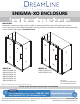
A B B C A E ! IMPORTANT INFORMATION REGARDING THE INSTALLATION OF THIS SHOWER DOOR D PANEL DOOR F Right hand door installation shown as an example A B C Guide Rail Brackets must be firmly attached to the wall. Installation into a stud is strongly recommended. All of the guide rail bracket set screws must be tightened. Thread Lock must be applied to both stopper set screws. Panel-side stopper must be installed into the pre-drilled stopper hole in the upper guide rail.
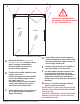
Reinforcement for Enigma Series Heavy Glass frameless sliding shower door Install studs OR install 2”x 6” wood blocking between the studs where the Guide Rail Brackets will attach to the wall d Stu or 2” ” X6 X 2” 6” measured from threshold* (see list below) ©2018 DreamLine.
Preparation 1. Prior to installation, examine all boxes and packages for shipping damage and compare the piece count with the packing slip. After opening all boxes and packages read this introduction carefully. Check that all of the necessary parts are included in the package by checking off the components on the “Detailed Diagram of Shower Door Components”.
Tools Level Drill bit (Ø1/8") (3mm) Tape Measure Drill bit (Ø1/4") (6mm) Pencil Drill bit (Ø3/8") (10mm) Drill bit (D=5/16") (8mm) Silicone Phillips Screwdriver Painter’s Tape Hammer Power Drill Razor Knife or Professional-grade Glass suction cup Chop saw Tip: Measure the finished opening before ! proceeding with the installation to be sure that the correct model size has been ordered.
Detailed Diagram of shower door components 10 9a 9b 11 1 12 8 7 2 4 3 13 The glass surface with the ClearMax™ label must be installed to face inside of the shower 28 14 5 15 16 6 27 17 18 19 26 30 Packing List DESCRIPTION QTY PART# DESCRIPTION QTY 01 Door stopper 2pcs 13 Bumper strip 1pc 02 Stationary glass 1pc 14 Anti-water strip 2pcs 03 Upper Guide rail 1pc 15 Anti-splash threshold 1pc 04 Roller 4pcs 16 Threshold cap 1pc 05 Door Glass 1pc 17 ST4.
Detailed Diagram of shower door components for 72” model width 7 1 8 2 The glass surface with the ClearMax™ label must be installed to face inside of the shower 4 9 5 10 21 28 24 11 12 13* 27 6 14 15 17 18 23 26 19 30 22 Packing List DESCRIPTION DESCRIPTION QTY PART# 01 Door stopper 2pcs 15 Anti-splash threshold 1pc 02 Stationary glass 1pc 16 Threshold cap** 1pc 04 Roller 4pcs 17 ST4.2x40 Countersunk screw 4pcs 05 Door Glass 1pc 18 ST4.
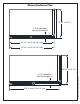
Shower Enclosure Plan 32-1/2” or 34 1/2" 2-3/4” minimum threshold required 44-3/8 “ min to 48-3/8” max 50-3/8 “ min to 54-3/8” max 32-1/2” or 34 1/2" ©2018 DreamLine.
Shower Enclosure Plan 32-1/2” or 34 1/2" 2-3/4” minimum threshold required ! When constructing or installing a shower base, consider how the thickness of the wall treatment (wallboard, tile, etc.) will affect where the shower enclosure will sit on the threshold. Compare the overall outside dimensions of the shower enclosure model size as shown on the “Shower Enclosure Plan” with the finished threshold before proceeding with the installation.
Installation steps 1. Attach the three Wall Brackets (#19) to the Return Panel (#27). The bolt side of each Wall Bracket (#19) must face inside the shower. (Fig 1) Outside Outside Outside Fig 1 <48",<60",<72" 2.
3. Outline the position of the Wall Brackets (#19) on the wall and the shower base or threshold. Carefully set the Return Panel (#27) aside. Remove the Wall Brackets (#19) from the Return Panel (#27). Place the brackets against the outlined positions and mark the holes on the wall and threshold for drilling. (Fig 3) 1 2 3 4 Fig 3 4. Drill the holes in the wall using a Ø5/16” drill bit and insert the Wall Anchors (#9b) for two of the Wall Brackets (#19).
5. Place the Return Panel (#27) back in the designated position and assemble the Wall Brackets (#19) onto the glass. Use the provided gaskets and sleeve to protect the glass. (Fig 5) 6. Measure the distance from the finished wall to the inside surface of the installed Return Panel Glass (#27). This distance will represent the finished opening size “W” that will be used to calculate the finished cut dimension for the Upper Guide Rail (#03). (Fig 6) W W Fig 5 Fig 6 7.
8a. Attach the Upper Guide Rail (#03) to the Stationary Glass (#02) with the Glass Brackets (#07) and tighten the bolts into the predrilled holes in the Upper Guide Rail (#03). Make sure both adjustment disks are installed in the same direction with the high spot towards the door end. (see *Note below) Make sure that the guide rail is attached parallel to the top edge of the stationary panel glass. (Fig 8.3) *NOTE: The outer glass bracket disk has an eccentric bushing for adjustment.
9. Place the Stationary Glass (#02) with the Upper Guide Rail (#03) onto the threshold and position it against the wall. Fasten the Upper Guide Rail (#03) to the Return Panel (#27) using the Glass Connector (#28). (Fig 9a) Tighten the set screws to secure the guide rail bracket sleeve to the Glass Connector (#28). (Fig 9a) Make sure the Stationary Glass (#02) and the Upper Guide Rail (#03) are level.
ATTENTION: This step shows the Small Stationary Glass Bracket (#21) installation for the 72” model only (not included with the 48“ or 60” model). (Fig 10) 10. If the model width is 72” and includes the Small Stationary Glass (#23), attach the Small Stationary Glass Bracket (#21) to the Upper Guide Rail for 72” (#24) between the Door Stopper (#01) and the Guide Rail Bracket (#08) as shown in Fig 10. This bracket will be repositioned during the installation of the Small Stationary Glass (#23).
12. If installing the 72” model: Unscrew the disk from the Small Stationary Glass Bracket (#21) and loosen the set screw that secures the bracket to the guide rail. If necessary, slide the Door Stopper (#01) away from the area so that it will not interfere with the placement of the Small Stationary Glass (#23). (Fig 12.2) Position the Small Stationary Glass (#23) onto the threshold and carefully butt it up against the installed Return Panel Glass (#27).
14. Make sure the Stationary Glass (#02) is parallel to the front edge of the threshold. Level it vertically (plumb) and mark the position on the threshold. Slide the Guide Block (#12) into the notch in the Stationary Glass (#02), and align flush with the edge. Mark its position and also mark the hole for drilling using a pencil (or center punch).
16. Drill a hole for the Wall Bracket (#19) using a Ø5/16” 1 Drill the holes for the Guide Rail Brackets (#08) using a Ø3/8” (10mm) drill bit and insert the Wall Anchors (#9a). (Fig 16.3**-16.4**) 3** (8mm) drill bit and insert the Wall Anchor (#9b). (Fig 16.1 and 16.2) *For the 72“ model, drill an Ø1/8” hole for an acrylic base (or Ø5/16” for tile) for the Wall Bracket (#19) for the Small Stationary Panel Glass (#23). (Fig 16.
18. To install the Guide Block (#12): Loosen the set screw and remove the guide block face plate. Apply silicone to the underside of the Guide Block (#12) and screw the Guide Block (#12) to the threshold as described below: *NOTE: ◾For installation into an Acrylic Threshold: drill an Ø1/8”(3mm) hole and use the ST4.2 x 40mm Countersunk Screw (#17) OR ◾For installation into a Tile Threshold: drill a Ø5/16”(8mm) hole, install Wall Anchor Ø5/16” (#09b) and use the ST4.
19. If installing the 72” model, repeat Step #18 for the Small 1 Stationary Glass Bottom Bracket (#22). Loosen the set screw and remove the guide block face plate. 2 use a pencil or a center-punch to mark the hole *NOTE: *see note ◾For installation into an Acrylic Threshold: drill an Ø1/8”(3mm) hole and use the ST4.2 x 40mm Countersunk Screw (#17) OR ◾For installation into a Tile Threshold: drill a Ø5/16”(8mm) hole and use the ST4.
20. Reposition the Stationary Glass (#02) and Upper Guide Rail (#03) onto the threshold and fasten the sleeves of the Guide Rail Brackets (#08) to the installed bracket on the wall and the Glass Connector (#28). Tighten the set screws on the Guide Rail Brackets (#08) to secure the Upper Guide Rail (#03). Position the bracket set screws so that they are accessible from the top and bottom. (Fig 20.1 and Fig 20.2) 1 Assemble the Wall Bracket (#19) at the bottom corner of the Stationary Glass (#02).
21a. For the 48” or 60“ model size: Measure the distance from the edge of the Guide Block (#12) to the wall. This distance will be “X”. Cut the Anti-Splash Guard (#15) to the size of: (X) + 3/8”. (Fig 23a) 21b. For the 72” model size: Measure the distance between the edge of the Guide Block (#12) to the edge of the Small Stationary Glass Bottom Bracket (#22). This distance will be “L”. Cut the Anti-Splash Guard (#15) to the size of: (L) + 3/4”.
23. Secure the Anti-Splash Threshold (#15) to the shower base with several pieces of painter’s tape to hold it in position and tight to the based until the silicone fully cures. (Fig 25) Fig 25 24. Attach the Guide block face plate to the installed face plate ENIGMA-XO Shower Enclosure manual Ver 1 Rev 1 01/2018 ©2018 DreamLine. All Rights Reserved Guide Block (#12) and tighten the set screw with the supplied allen wrench. Use the supplied Decorative caps to cover the screw holes.
25. If installing the 72” model: Apply a thin bead of silicone to the edge of the Small Stationary Panel Glass (#23) and carefully butt it up against the installed Return Panel Glass (#27). Attach the Small Stationary Panel Glass (#23) to the Upper Guide Rail (#03) using the Small Stationary Glass Bracket (#21). Attach the face plate to the Wall Bracket (#19) on the threshold. Use some painter’s tape to secure the corner until the silicone cures. (Fig 27 and Fig 28) 1 2 4 5 3 Fig 27 outside 26.
! NOTE: DO NOT attach the handle to the door glass until instructed to do so. DO NOT attempt to lift the door glass with the handle as this may result in damage to the glass and/or serious personal injury. 27. Attach the two Rollers (#04) to the Door Glass (#05) with the wheels facing the outside of the shower. Align the safety set screw towards the top for easier access (See Fig 29 and page 30 for details).
. Attach the two remaining Rollers (#04) into the holes in the Door Glass (#05) beneath the Upper Guide Rail (#03). Adjust these Rollers (#04) to make contact with the Upper Guide Rail (#03). Apply Thread Lock Adhesive (#26) to the bolts and safety set screws. Align the safety set screw towards the bottom(Fig 30.4) for easier access to retighten after installation.
1 29. Press the Anti-Water Strip (#14) onto the vertical edge of the Stationary Glass (#02) and the Door Glass (#05) (Fig 24.1). Press the Bumper Strip (#13) onto the vertical edge of the Door Glass (#05) (48” and 60“ model). (Fig 32.2) For the 72” model: Attach Anti-Water Strip (#14) to the edge of the Small Stationary Glass (#23). The Bumper Strip (#13) is not necessary with the 72” model (Fig 33.3*).
Door Stopper Installation: 1. 2. 3. 4. 5. 6. Remove the set screw Slide the Door Stopper (#01) onto the Upper Guide Rail (#03) Align with stopper hole (stationary panel side only) Apply Thread Lock Adhesive (#26) to the set screw threads Tighten screw into the stopper hole (stationary panel side only) Correctly position the door side stopper and tighten the set screw with Thread Lock Adhesive (#26) (Fig.
. To install the Bumper (#30) with the 3M tape: position the Bumper (#30) onto the threshold and against the wall on the stationary panel side of the installation. (For 72” model, this will be the side of the opening with the large stationary panel) Remove the 3M Tape and position the Bumper (#30) onto the threshold against the Wall Bracket (#19). (Fig 34) ! NOTE: The surfaces need to be clean and free of construction debris before installing the bumper.
. To install the Bumper (#30) with the screw method: position the Bumper (#30) onto the threshold and against the wall on the stationary panel side of the installation. (For 72” model, this will be the side of the opening with the large stationary panel). and mark the position of the hole onto the wall. Drill a Ø5/16” hole and insert the wall anchor. Remove the 3M Tape and position the Bumper (#30) onto the threshold against the Wall Bracket (#19) and attach using the ST4.2 x 40 Countersunk screw.
. Apply a good quality mildew-resistant silicone along the interior perimeter where the glass meets the wall and threshold and also along the Anti-Splash Guard (#15). (Fig 36) Please allow 24 hours for the silicone to fully cure before using the shower. 24 Hours ! ENIGMA-XO Shower Enclosure manual Ver 1 Rev 1 01/2018 ©2018 DreamLine.
Roller adjustment procedure for Enigma, Enigma-X and Enigma-XO To achieve minimal clearance beneath the door glass without making contact with the bottom guide block and creating a good seal with the wall. Have at least two 3/16” shims or wedge shims (to maintain space beneath the door glass) and an assistant available to help with this procedure. Adjust only one wheel at a time and you may need to perform these steps more than once to get the desired results.
Product Maintenance BASES and BACKWALLS: To ensure long lasting life for your acrylic back walls: wipe them off after each use with a soft cloth. To clean the acrylic back walls use non-abrasive sprays or cream based cleaners. Avoid the use of aerosol spray cleaners. Never use abrasive cleansers, metal brushes or scrapers that could scratch or dull the surface. GLASS: To ensure long lasting life for your glass shower products: wipe them off after each use with a soft cloth.
For more information on DreamLine® Shower Doors and Enclosures please visit DreamLine.com ©2018 DreamLine. All Rights Reserved TEL: 866-731-2244 FAX: 866-857-3638 DREAMLINE.