
Manual


17ENIGMA-XO Shower Enclosure manual Ver 1 Rev 1 01/2018
©2018 DreamLine. All Rights Reserved
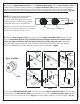
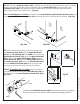
Fig 14a
Fig 14b
1 2
Fig 15
3*
for 72” model
base
sleeve
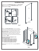
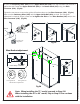
Separate the Guide Rail Bracket (#08) base from the sleeve by loosening
the set screws. Leave the sleeves on both ends of the upper guide rail.
15. After marking the positions of all the hardware, set
the Stationary Glass (#02) with the Upper Guide Rail
(#03) aside. (If installing the 72” model, also remove the
Small Stationary Glass (#23) from the Upper Guide Rail
(#03). Remove the Guide Rail Brackets (#08) from the
Upper Guide Rail (#03) and the Wall Bracket (#19) from
the Stationary Glass (#02). Place the Wall Bracket (#19)
and one Guide Rail Bracket (#08) back to the outlined
positions on the wall and mark the holes for drilling.
*NOTE: If installing the 72” model, perform the same
procedure to mark the hole for the Wall Bracket (#19) on
the threshold for the Small Stationary Panel Glass (#23).
(Fig 15.3)
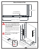
14. Make sure the Stationary Glass (#02) is parallel to the front edge of the threshold. Level it vertically
(plumb) and mark the position on the threshold. Slide the Guide Block (#12) into the notch in the
Stationary Glass (#02), and align flush with the edge. Mark its position and also mark the hole for
drilling using a pencil (or center punch). (Fig 14a)
Note: If installing the 72” model, also position the Small Stationary Glass Bottom Bracket (#22) with
the edge of the Small Stationary Glass (#23) and mark its position and the hole for drilling. (Fig 14b)