
Manual
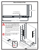


18ENIGMA-XO Shower Enclosure manual Ver 1 Rev 1 01/2018
©2018 DreamLine. All Rights Reserved
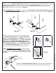
Fig 16
1
3**
4**
Ø5/16”
(8mm)
2
Ø3/8”
(10mm)
see Note**
5*
for 72” model
Ø1/8”
(8mm)
see Note*
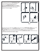
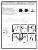
16. Drill a hole for the Wall Bracket (#19) using a Ø5/16”
(8mm) drill bit and insert the Wall Anchor (#9b).
(Fig 16.1 and 16.2)
*For the 72“ model, drill an Ø1/8” hole for an acrylic base
(or Ø5/16” for tile) for the Wall Bracket (#19) for the Small
Stationary Panel Glass (#23). (Fig 16.5)
Drill the holes for the Guide Rail Brackets (#08) using a
Ø3/8” (10mm) drill bit and insert the Wall Anchors (#9a).
(Fig 16.3**-16.4**)
1
2
3
4
Fig 17
for 72” model
5
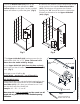
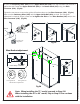
17. Fasten the Wall Bracket (#19) to the wall using the ST4.2×55 Truss Head Screw (#18). (Fig 17.1)
For the 72“ model, repeat this step to attach the Wall Bracket (#19) for the Small Stationary Panel
Glass (#23). Use an ST4.2x25 screw into an acrylic base or ST4.2x40 with an anchor for tile (Fig 17.5).
Attach the base part of one Guide Rail Bracket (#08) to the wall using the ST6×65 Large Truss Head
Screw (#10) (Fig 17.2). Note that the adjustment set screws on the bracket must be aligned vertically
for easier access to tighten and adjust for level after the glass is installed. Fasten the Upper Guide
Rail (#03) to the Return Panel (#27), connecting the sleeve of the Guide Rail Bracket (#08) to the
Glass Connector (#28) (Fig 17.3 and 17.4). Align the set screws vertically and tighten. (Fig 17)
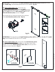
**NOTE: Step #16 has an option for installing the
guide rail brackets to the wall using anchors. However, the
manufacturer strongly recommends installing these
heavy doors to the studs or to pre-installed 2”x 6”
wood reinforcement behind the wall in the area where
the guide rail brackets will be attached to the wall.
!
**For the recommended installation into a stud,
drill a Ø1/4” hole up to the stud, do not use wall
anchors, and let the screw bore into the wood.
(Fig 16)