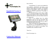
Dear Customer, DashDAQ Series II Congratulations! You have just purchased the most powerful, sophisticated, and easy to use automotive data logger ever created. The DashDAQ Series II gives everyone access to the powerful information embedded in their vehicle. When it comes to automotive performance, knowledge is horsepower. The DashDAQ Series II works with any OBDII vehicle. It can also be fitted to any other vehicle using optional add-ons.
Table Of Contents 1 1.1 1.2 1.3 1.4 1.5 1.6 1.7 1.8 2 2.1 2.2 2.3 2.4 2.5 3 3.1 3.2 3.3 3.4 3.5 3.6 4 4.1 4.2 4.3 4.4 4.5 4.6 4.7 4.8 4.9 5 6 Installation...................................... 9 SAFETY FIRST! ..................................................... 9 Attaching Windshield Mount ................................... 9 Windshield Mounting ............................................ 10 Mounting suggestions:.......................................... 10 Cable Routing.............................
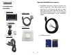
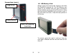
Components Optional DashDAQ Accessories • DashDAQ Accessory Cable for analog and serial connectivity. This cable allows you to add two 0-5 volt sensors, as well as many other third party data collection devices. The DashDAQ Accessory cable can be obtained from Drew Technologies, or your DashDAQ dealer.
IMPORTANT! THIS IS A HIGH PERFORMANCE PRODUCT, USE AT YOUR OWN RISK Do not use this product until you have carefully read the following agreement. This sets forth the terms and conditions for the use of this product. The installation of this product indicates the BUYER has read and understands this agreement and accepts its terms and conditions. This agreement takes precedence.
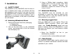
3. Using a Phillips head screwdriver, lightly tighten each of the four screws. Note: Over tightening can possibly damage your DashDAQ. Tighten the screws so they are snug, no more. 1 Installation 1.1 SAFETY FIRST! The installation of the DashDAQ must be done in such a manner that it does not interfere with the safe operation of your vehicle.
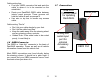
Cable routing tips: • Find your OBDII connector first and work the cable to where it is to be mounted on the windshield. • Route your DashDAQ OBDII cable between interior panel grooves. These grooves will hold the cable as well as conceal it. • Use wire or zip ties to bundle any excess cable. 1.7 Connections USB Port. This port used for updating DashDAQ. Cable routing “Don’ts” • Don’t let your cable dangle by your feet. • Don’t let the cable hang free.
Connections (cont.) 1.8 SD Memory Card USB Ports Always insert and remove the memory card with the DashDAQ powered off. The SD Memory card needs to be inserted with the gold connections facing towards you as you look at the screen. Press the card into the DashDAQ until you hear a click. If the card sticks out at all, it has not been pushed in all the way. Power Button MMC SD Memory Card Slot To remove, press the card in until you hear the click again. Release and the card will come all the way out.
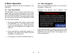
2 Basic Operation 2.2 Menu Navigation This section describes the basic operation of the DashDAQ. When your DashDAQ first starts up, a boot screen will appear. Please wait. 2.1 Low Power Mode Whenever the warning screen appears, read carefully. The DashDAQ has a low power mode built in as a power and time saving convenience. This mode can be activated from the small black button on the front left of the DashDAQ. Low power mode keeps you from having to wait for the DashDAQ to start up.
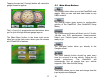
Tapping the tap the [I Accept] button will cause the gauge screen to appear: 2.3 Main Menu Buttons The [Diags] button takes you to the DashDAQ code reader. Here you can view and clear codes on any OBDII vehicle. The [Setup] button gives access to configuration options of the DashDAQ. (See DashDAQ Setup Menu) The [<<] and [>>] arrow buttons at the bottom allow you to cycle through different gauge layouts.
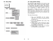
2.4 Menu Map 2.5 New Vehicle Setup The DashDAQ was designed to be used on any OBDII vehicle. OBDII vehicles have many “signals” or “parameters” that can be viewed. Each vehicle you connect the DashDAQ into will have a different set of parameters or signals available. Run the New Vehicle function every time you plug the DashDAQ into a different vehicle. If this is not done, parameters may show up on the list that don’t work and parameters that are available may not be displayed. The New Vehicle setup: 1.
3 Gauge Setup & Navigation 3.2 Assign a Signal to a Gauge This section describes how to setup gauges and navigate. Before specifying what signal you would like a gauge to display, make sure the New Vehicle procedure has been completed. 3.1 Navigating Gauges: 1. To assign a signal to a gauge, select a gauge screen. Tap on the gauge where you would like a signal to display. This screen will appear: To access DashDAQ gauges, tap on [Gauges] from the Main Menu.
3.3 Set Gauge Min/Max Values 3.4 Set Gauge High/Low Warning The DashDAQ allows users to specify the data range for each gauge. Tap on the [Minimum] button to set the bottom value for a gauge. Tap on the [Maximum] button to set the top of the gauge. The High/Low Warning allows users to set the visual representation of “redline” on a gauge. When you tap on either [Minimum] or [Maximum] this screen will appear: Tap in the desired value. Tap [+/-] to make this value negative.
The DashDAQ allows users to assign different colors to the signals assigned to a particular gauge. The signal will be displayed in the color chosen. To change color values: 1. Tap on a signal box . 2. Tap on the red, green, and blue swatch in the corner of the box. 3.6 Data Logging The DashDAQ is not only a powerful gauge display, it can also log and save all information represented on the gauges. This information is saved to a Microsoft Excel *.csv file to an inserted SD memory card.
the signals displayed on the gauges. 3. When finished with your log session tap [End Log]. Your results are now saved to the memory card. Each time you go through the above three steps, the DashDAQ saves one file on the SD memory card. The file is saved in a directory called “log.” Each saved file has a log prefix. The default prefix is “log” and can be changed to your liking. 3. Enter the desired name of the log file prefix. Example: TestDrag. Now tap [Save].
3. Tap on a blank space that corresponds to the letter you would like the driver assigned to. 4 DashDAQ Setup Menu This section describes the setup menu. 4.1 Installed Devices The Installed Devices section of the setup menu is what makes DashDAQ truly unique. Software drivers are written by Drew Technologies so that third party devices like Innovate Motorsports, Blackline GPS, and PLX Devices can be connected to DashDAQ.
6. To select the Innovate LC-1, use the [<] or [>] buttons to navigate to the “Wideband” selection. To make use of the driver after it has been selected: 1. Tap on [Gauges] from the Main Menu. 2. Tap on a gauge you would like to assign the Innovate LC-1 signal to. 3. Tap [Assign Signal]. 4. Use the [<] or [>] buttons to navigate to the Innovate LC-1 heading. Tap [Air-Fuel Ratio] to highlight. 7. Tap [Innovate LC-1] to highlight the Innovate LC-1 driver. Tap [Save]. 8. Tap [Save] again.
4.2 Clock 4.3 Install From SD Card The clock setup option allows the user to set the on board clock to current time and date. This information will be time-stamped into all log files that you make. This setup option allows you to install various user licenses, drivers, and Config files. These files can be saved with the Backup To SD Card option. To install any of these three items: To set the time and date: 1. Tap on [Setup] from the Main Menu.
4.4 Backup To SD Card 4.5 Startup Splash Screen Backup to SD is the setup option that allows you to backup various user specific setting of the DashDAQ. One example is backing up the gauge setup for all dashboard themes and gauge layouts within each theme. This is done by backing up “Config File.” This setup option allows you choose which image file you would like to be displayed when the DashDAQ starts up. To back a specific license, driver, or config file: 1. Tap on [Setup] from the Main Menu.
4.7 Dashboard Theme 4.8 Backlight Brightness The DashDAQ has a very powerful graphical interface that allows its users to change the look and feel of the gauges. Each theme has different gauge layouts. The Dashboard Theme option gives users the ability to switch between these “skins.” By tapping on a specific theme name and tapping [Save], the new skin will be instantly loaded. The Backlight Brightness setup option allows you to change how bright the screen is. Gauge layouts themes.
4.9 Logfile Prefix 5 Diagnostic Code Reader The Logfile Prefix is the name that is attached to the beginning of a log file. When you tap “Start Log” from a gauge screen a file is instantly created on your SD card in Microsoft Excel Format. This file is given a name based on the log file prefix and the number of log files already on the memory card. This allows you to change the name of your log files for specific events, ex: Milan_10_10_2007.
6 Performance Measurements 1/4-mile, 1/8-mile, and 0-60mph times can be attained with the DashDAQ. All that is needed to calculate these measurements is a vehicle speed sensor signal (OBDII/Aftermarket ECU’s) or a speed signal from a GPS receiver. If you want to measure performance: 6. Tap [Yes] if you would like to clear the codes and turn your check engine light off. Note: This does not solve any underlying vehicle issues. 7. Tap [No] if you do not want to clear the codes. 1.
4. Bring your vehicle to a stop and tap [Start]. When the drag-strip “tree” turns green, accelerate. 5. The measurement will automatically end and display the result when you have completed the run. 7 Dyno Calculator The Dyno Calculator allows you to measure vehicle horsepower and torque on the fly. These two measurements are assignable to any gauge. The ability to assign horsepower and torque values to any gauge also allows you to log this information alongside any other available signals.
4. Tap [Change]. This screen appears: 7. Tap [Dyno Calculator] to highlight the Dyno Calculator driver. Tap [Save]. 8. Tap [Save] again. Tap [Save] once more at the Installed Device setup window. The Dyno Calculator needs 3 signals to calculate horsepower and torque: vehicle speed sensor, vehicle rpm sensor, and vehicle weight. These variables can be defined in the Parameters menu from the Main Menu. Here’s how: 1. Tap on [Parameters] from the Main Menu. 2.
3. You will need to tap on each signal and tap [Change] to specify the values of each. The DashDAQ is row ready to calculate horsepower and torque for your vehicle. Navigating to the Gauges screen will allow you to assign either signal to any gauge. For example: 1. From the Main Menu, tap on [Gauges]. 2. Tap on the gauge you would like to assign horsepower or torque to. 3. Tap on [Assign Signal]. 4. Use the [<] or [>] buttons to find the “d- Dyno Calculator” option. 5.
Fuel ratio and Fuel Density will be the same for stock OBDII vehicles and are already preset. The Vehicle Speed sensor, and Mass Air Flow sensor will need to be defined, here’s how: 1. Tap on [Parameters] from the Main Menu. 2. Navigate to the “Fuel Economy Calculator” option by taping on the [<] or [>] buttons. 5. Tap [Driver]. 6. To select the Fuel Economy Calculator, use the [<] or [>] buttons to navigate to the “Calculator” selection. 3.
5. Tap on the desired measurement and tap [Save]. Tap [Save] again to view the calculation on the gauge. 9 Parameters From the Main Menu you can access the Parameter menu. This menu allows you to change the scaling and other options associated with an installed driver. Some examples include: changing offsets for analog inputs, changing OBDII units to metric, etc. The Parameters menu allows you to customize how the data is displayed. 11 Updating DashDAQ Your DashDAQ’s software is completely updateable.
4. Click on [Browse my computer for driver software]. You will see this message: 3. Windows will do a preliminary search for the driver, but will not find one. This screen will appear: 5. Click on [BrowseQ] and highlight your CDRom drive. Click [Ok]. Now click [Next]. You will see this screen: 6. Click on [Install this driver software anyway]. Windows will now go through the install procedure and will tell you when the driver has successfully installed.
7. The Select DashDAQ Tool Package screen will appear: 11.2 Update your DashDAQ: 1. Connect the USB cable to the single USB port on the left as you look at the DashDAQ screen, and then to your computer. 2. Go to Start>Programs>Drew Technologies, Inc> DashDAQ Update Tool 8. Select the firmware file that was downloaded. Click [Open]. Your DashDAQ will begin updating. 3. Click on [Check Web For Updates]. This will download the latest firmware for your DashDAQ. 4.
12.2 Technical Specifications 12 APPENDIX Display Resolution 12.1 Support System Processor Vehicle Bus Processor RAM Flash Memory Expansion Device I/O Please be sure to reference our online FAQ’s. All support questions can be answered at the online forums at www.dashdaq.com. These forums are constantly monitored, and will provide you with the fastest answers.
12.3 Limited Warranty 12.4 Accessory Cable Pin Out Drew Technologies, Inc. guarantees that every DashDAQ Series II is free from physical defects in material and workmanship under normal use for one year from the date of purchase. Warranty card must be mailed within 90 days of initial purchase to activate warranty. If the product proves defective during this warranty period, email Drew Technologies Customer Support (support@drewtech.com) in order to obtain a Return Authorization number and form.
61