
Instruction manual


51
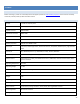
APPENDIX A: ACCESSORY CABLE PIN OUT
1
Red Vehicle Power In/Out
If DashDAQ is connected via
OBD2 cable, this is the source
for vehicle power. If OBD2 is not
connected, vehicle power must
be applied here. Warning! Do
not attempt to power any
device from this output that
draws more that 500ma of
current. Failure to observe this
restriction could result in
permanent un-repairable
damage to your DashDAQ.
2
Orange Serial Port 1 Rx Connect to pin 3 of PC DB-9
3
Yellow Serial Port 2 Tx Connect to pin 2 of PC DB-9
4
Blue Serial Port 2 Rx Connect to pin 3 of PC DB-9
5
Brown Serial Port 1 Tx Connect to pin 2 of PC DB-9
6
Black Case Ground 1Meg Ohm to Gnd. For cable
shielding. Do not use as a
Ground.
7
White Analog input 2 0.0 to 5.0 Volt input
8
Pink 5V @ 500ma Output Resettable fuse protected.
9
Green Analog input 1 0.0 to 5.0 Volt input
1
0
Shield Ground This is the signal ground.
Connect to pin 5 of PC DB-9
Note: For future compatibility tie 6 and 10 together.