
Operating instructions


DRI-AIR INDUSTRIES, INC.
OPERATING MANUAL - APD 10-13, HPD 10-13 DRYERS
Revision 10/8/02
Page 19
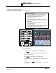
Check the limit first by pressing the SET button on the
temperature control and holding until AL is displayed. The
setting shown indicated the amount over set point that the
alarm will be actuated. It is factory set to 50°F (30°C) and
should not be set below 30°F (16°C) or it will actuate too soon.
If the temp exceeds the set point check the following:
1. Remove the hose from the top of the hopper to check air
flow. There should be air flow out of the hopper with a
suction on the hose. If there is little or no flow, check the
inlet hose.
2. Inspect the filter to make sure that it is clean and not
affecting the air flow.
3. Check the solid state relays to see if one of the solid
state relays has failed on. Using an ammeter or
voltmeter on the output to the heater, see if there is
power when the LED is not lit which will indicate a failed
relay.
4. Check the Zone Valve position.
The Dri-Air Pneumatic Zone Valve is designed to provide very
little flow restriction and no leakage. It incorporates an Air-
Flow Diversion Valve controlled by a single solenoid valve.
The solenoid valve simultaneously actuates air cylinders on
each side of the Air-Flow Valve, altering air flow through the
dryer. When a new regeneration cycle begins, the valve
diverts air to the newly regenerated tower and exhausts wet
regeneration air from the desiccant bed being regenerated.
This allows for a constant supply of dry air to flow to the
material hopper. Air pressure should be kept at 60 psi to
ensure reliable operation.
Trouble shooting is easy. To access the Air-Flow Diversion
Valve, remove either side panel on the dryer cabinet. The
valve is located in the “Blower Section”, positioned on the
upright separating the blower section from the tower section of
the cabinet. To determine which zone the valve is set to,
locate the two ports on the top of the valve (one on each end)
for exhausting wet regeneration air and place your hand over
an exhaust port to feel for air flow. Air will be flowing from the
port that is set to regeneration. (Note, as you face the dryer’s
electrical panel enclosure, the exhaust port on the right side of
the valve is for ZONE 1 and the port on the left side is for
ZONE 2.) Compare your findings to the lighted ZONE
Position LED on the control panel display to ensure that they
correspond with each other. If they do not correspond or if air
is exhausting from both ports, the valve is not working
properly. Check the following:
DRI-AIR
PNEUMATIC ZONE
VALVE
TROUBLESHOOTING