READ AND SAVE THESE INSTRUCTIONS ® VAPOR-LOGIC2 MICROPROCESSOR HUMIDIFIER CONTROL SYSTEM INSTALLATION INSTRUCTIONS and OPERATIONS MANUAL
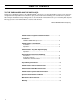
TABLE OF CONTENTS TO THE PURCHASER AND THE INSTALLER: Thank you for deciding to purchase the VAPOR-LOGIC®2 microprocessor-based humidifier control system. We have designed and developed this microcontroller to give you total satisfaction and many years of trouble-free operation. Observing the installation and operating practices described in this manual will assure you of achieving that objective. We urge you to become familiar with the contents of this manual.
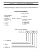
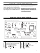
VAPOR-LOGIC®2 PROGRAM CODE NOMENCLATURE A six digit VAPOR-LOGIC2 program code appears on the front of the control cabinet and on the wiring diagram inside of the control cabinet. The program code specifies the parameters necessary for the VAPOR-LOGIC microprocessor to control your system. An explanation of the program code is detailed below. VAPOR-LOGIC2 PROGRAM CODE A. Type of water level control: VSDI with manual drain = D Probe with manual drain = M Probe with auto drain = A EOS/DI drain = E B.
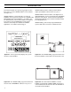
INTRODUCTION This manual explains the operation of and gives instructions for the use of the VAPOR-LOGIC®2 microcontroller. (See figure 4-1.) VAPOR-LOGIC2 is a custom microprocessor-based humidifier control system developed to be compatible with DRI-STEEM single stage humidifiers. (See figures 4-2, 4-3 and 4-4 below.) The versatile software is configured to meet the needs of humidification system control variations and to adapt to a multitude of humidifier applications.
VAPOR-LOGIC®2 CONTROL BOARD INSTALLATION The VAPOR-LOGIC2 control board is shipped factory mounted within a control cabinet with all internal wiring completed. All software has been custom programmed into your VAPOR-LOGIC2 system according to the original order requirements. Refer to the VAPOR-LOGIC2 control board drawing for detail of the board and connection points. (See figure 5-1.) Never run control system wires bundled with, or in the same conduit as, line voltage wires.
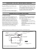
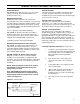
VAPOR-LOGIC®2 OPERATION Figure 6-1 : Conductivity probe system page 8.) Probe C provides low water protection for the heating elements. If the water level falls below probe C, the heat source is de-energized. (See figure 6-1.) In addition to controlling the water level, VAPOR-LOGIC2 determines when the heat source is energized. If there is a call for humidification, even during the fill cycle, the heat source will stay on to provide continuous output.
VAPOR-LOGIC®2 KEY PAD / DIGITAL DISPLAY OPERATION UP ARROW The UP ARROW key is used, in the AUTOMATIC mode, to transfer one of the automatic scrolling items on the lower line to the upper line for constant monitoring. The item selected will be updated every few seconds and will remain isolated on the upper line while the other functions will continue scrolling on the lower line.
VAPOR-LOGIC®2 KEY PAD / DIGITAL DISPLAY OPERATION Once in the Main Menu, use the SET key to scroll through the items until the item you want is shown. Use the UP and DOWN ARROW keys to change or set the parameter. A service timer is included as a reminder to perform periodic maintenance and service to the humidifier. The SERVICE timer display is included in VIEW and SCAN displays. The SERVICE timer advances when the control is in the AUTO mode.
SENSING DEVICE PLACEMENT AND WIRING On/Off Humidistats* DRI-STEEM may provide three types of on-off controls: a wall or a return air, duct mounted humidistat, or a pneumatic/electric relay. Modulating Humidistats* Humidistats can be supplied for either wall or duct mounted applications. These humidistats are powered by a 21 VDC supply provided by the VAPOR-LOGIC2 control board. A 0-15 VDC modulated control signal is returned to the VAPOR-LOGIC2 control board which modulates the output of the humidifier.
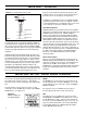
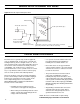
SENSING DEVICE PLACEMENT AND WIRING Figure 10-1: Cold snap transmitter placement Window framing Thermostat control wires Double pane window glass Surface mounting thermostat temperature control box to wall Typical sensor umbilical cord routing Temperature sensor tip, secured to inside surface of window glass using clear RTV silicone adhesive around tip OM-337 PROPER WIRING PROCEDURES Electrical "noise" is generated by electrical equipment, such as switching loads, electric motors, solenoid coils, weld
VAPOR-LOGIC®2 AUTO SCROLL INFORMATION The following pages contain information about the digital read-outs that VAPOR-LOGIC2 displays on the key pad. This includes a wide variety of present system conditions, faults, and programmable parameters that ultimately control the humidification system. The charts are organized based upon when or why the information is communicated. Auto Scroll: The items that will continuously scroll on the lower line during normal humidifier operation are listed below.
VAPOR-LOGIC®2 MAIN MENU INFORMATION Main Menu Descriptions: The Main Menu items are available by pressing the SET key while in either AUTO or STNDBY mode. The SET key also allows you to scroll through the items in the Main Menu. While in the Main Menu, you may view or change the system parameters by following the instructions on page 8. Note: If any of the options were not selected by the original customer humidifier order, that specific parameter would be removed from the Main Menu.
VAPOR-LOGIC®2 SYSTEM STATUS INFORMATION ' ,* ,7$ / ' ,6 3 / $ < 6 < 6 7 ( 0 6 7$ 7 8 6 5( $' 287 6 < 6 7 ( 0 6 7$ 7 8 6 ' ( 6 &5 ,3 7 ,2 1 "AUTO MODE" The system is in AUTO MODE, which allows for the normal operation of the humidifier. (Default mode at star tup.) "STANDBY MODE" The system is in STANDBY MODE, which turns off all control outputs during periods of servicing. Programming functions are available.
SYSTEM FAULT & DISABLE CONDITIONS Fault Conditions The system continuously monitors for a wide variety of FAULT conditions. When a FAULT occurs, the status of the system is changed to “FAULT” and the appropriate description appears in the lower line display. A FAULT condition shuts off all of the humidifier outputs. All faults deactivate the demand for heat. If the fault is a “FILL” fault, the line voltage must be interrupted to reset the system.
MAINTENANCE SERVICE RECORD DATE INSPECTED PERSONNEL OBSERVATION ACTION PERFORMED 15
TWO YEAR LIMITED WARRANTY DRI-STEEM Humidifier Company (“DRI-STEEM”) warrants to the original user that its products will be free from defects in materials and workmanship for a period of two (2) years after installation or twenty-seven (27) months from the date DRI-STEEM ships such product, whichever date is the earlier.