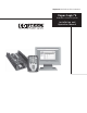
Important: Read and save these instructions.
$POUFOUT DRI-STEEM® Technical Support: 800-328-4447 Warnings and Cautions . . . . . . . . . . . . . . . . . . . . . . . . . . . . . . . . iv Overview Vapor-logic4 capabilities . . . . . . . . . . . . . . . . . . . . . . . . . . . . . . . . . . 1 Humidification system overview . . . . . . . . . . . . . . . . . . . . . . . . . . . 3 Vapor-logic4 board: . . . . . . . . . . . . . . . . . . . . . . . . . . . . . . . . . . . . . . 4 Keypad/display . . . . . . . . . . . . . . . . . . . . . . . . . . . . . . . .
$POUFOUT Options and features Duct high limit switch option . . . . . . . . . . . . . . . . . . . . . . . . 58 Modulating high limit transmitter option . . . . . . . . . . . . . . 58 Temperature compensation control option . . . . . . . . . . . . . 58 Auxiliary temperature sensor option . . . . . . . . . . . . . . . . . . 59 Tank preheat feature . . . . . . . . . . . . . . . . . . . . . . . . . . . . . . . . 59 Aquastat set point feature . . . . . . . . . . . . . . . . . . . . . . . . . . . .
War nings and Cautions WARNING Indicates a hazardous situation that could result in death or serious injury if instructions are not followed. CAUTION Indicates a hazardous situation that could result in damage to or destruction of property if instructions are not followed. mc_051508_1145 WARNING Read all warnings and instructions This page provides important safety instructions; it is intended to supplement — not replace — the humidifier's Installation, Operation, and Maintenance Manual (IOM).
Overview 7B Q P S M P H J D D B Q B C J M J U J F T Accurate, responsive control The Vapor-logic4 controller provides accurate, responsive RH control. PID control tunes the system for maximum performance. Modbus®, BACnet®, or LonTalk® allow interoperability with multiple building automation systems. Modbus is standard, and BACnet or LonTalk are available options.
Overview 7B Q P S M P H J D D B Q B C J M J U J F T Enhanced diagnostics include: Insert a USB flash drive into the Vapor-logic4 board’s USB port to perform software updates, download data logs, and back up and restore data.
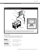
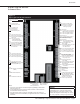
Overview )VNJEJGJDBUJPO TZTUFN PWFSWJFX Figure 3-1: Typical humidification system layout (GTS humidifier shown) Dispersion assembly Humidifier Vapor-logic4 keypad/display Connect a computer directly to the Vapor-logic4 board, or through a network, to use the Web interface Every humidification system with a Vapor-logic4 controller has a keypad/display connection and an Ethernet connection for connecting to a Web interface on a computer.
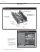
Overview 7B Q P S M P H J D C P B S E $PNQPOFOUT Figure 4-1: Vapor-logic4 control board Power to board connection USB connection Factory connection points for drain, steam valve, etc. Field connection points for transmitters, power vent, etc. Field connection terminal labels have a white border. Factory connection points for water level control, gas valves, etc.
Overview 7B Q P S M P H J D C P B S E $POOFDUJPOT Figure 5-1: Vapor-logic4 control board connections LED-1 (power indicator) LED-2 P19: Steam = Steam or hot water valve =Ground for blower and P16 triac SSR/BL = SSR (electric systems)/or Blower (gas systems) P1: 24VAC = Power to board = Ground for power return P2: Low = Low water probe Mid = Mid water probe Top = Top water probe = Ground for water probe P18: (all are triacs) CT/I4 = Contactor 4 (electric systems)/or Ignition module 4 (gas systems
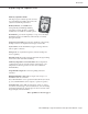
Overview ,FZQBE EJTQMBZ Figure 6-1: Using the Vapor-logic4 keypad/display Typical Home screen Change set point from the Home screen by pressing the Up or Down arrow keys until set point is highlighted (as shown here), press Enter, press Up or Down arrow keys to change value, press Enter to confirm Tank temperature Change Mode from the Home screen by pressing the Up or Down arrow keys until Mode is highlighted, press Enter, press Up or Down arrow keys to change, press Enter to confirm Fill icon shows wate
Overview 8FC JOUFSGBDF Figure 7-1: Using the Vapor-logic4 Web interface (Setup screen shown) Click on a tab label to move to another screen Click on CHANGE to change value To change value: Highlight value; type in new value; click on APPLY Click here to view alarms Click here to view messages Click on label to contract (–) or expand (+) menu item %3* 45&&. 7BQPS MPHJD *OTUBMMBUJPO BOE 0QFSBUJPO .
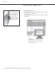
Installation 1SF JOTUBMMBUJPO $IFDLMJTU Figure 8-1: Vapor-logic4 control board detail ☐ See Figure 8-1 for field terminal block locations. Note that field wiring connection locations on the Vapor-logic4 board are surrounded with a white border. Full board ☐ See the figure on the next page for instructions on how to make wiring connections. ☐ See the wiring drawings and manuals that shipped with your humidifier. Terminals P-11 through P-16 have a white border on the Vapor-logic4 board.
Installation 1SF JOTUBMMBUJPO $IFDLMJTU [ Figure 9-1: Vapor-logic4 terminal block detail and connection instructions Tighten screw after wire is inserted. Maximum torque is 3 in-lb (0.34 N-m) Terminal block plug. Make connections when the plug is attached to the board, or remove for easier access. Pull plug straight up to remove. Remove insulation from end of wire and insert wire here. Vapor-logic4 board detail (see also Figure 5-1) P12 P13 P14 P15 P16 P11 24VDC RH N.O. C N.C.
Installation *OTUBMMBUJPO QSPDFTT The Vapor-logic4 board is designed to make installation very easy: t 5FSNJOBM CMPDLT UIBU SFRVJSF GJFME DPOOFDUJPOT BSF PVUMJOFE JO white. t 5FSNJOBM QMVHT DBO CF SFNPWFE UP BMMPX FBTZ BDDFTT XIFO inserting wires and tightening screws.
Installation *OTUBMMBUJPO QSPDFTT t $PNNVOJDBUJPO DPOOFDUJPOT – Vapor-logic4 keypad – Ethernet – Modbus – BACnet – LonTalk – Multiple-tank communication t 1SPHSBNNBCMF USJBD BOE SFMBZ t "SFB UZQF 4%6 EJTQFSTJPO GBOT PS TUFBN CMPXFST t $PNCVTUJPO BJS TXJUDI BOE QPXFS WFOU (54 TZTUFNT POMZ 2. Complete the Setup process. See instructions beginning on Page 28. 3. Start up humidifier(s). See instructions on Page 37.
Installation 4 U F Q o ' J F M E X J S J O H $POUSPM JOQVU Connect control input signal wiring by inserting wires into Terminal P11 (labeled 24vdc, RH, and ground) per the wiring diagram on the next page. Tighten screws; maximum torque is 3 in-lb (0.34 N-m). Figure 12-1: Terminal P11 Allowed inputs at Terminal P11 include: t 3) USBOTNJUUFS PS EFX QPJOU USBOTNJUUFS Transmitters provide a signal proportional to the RH or dew point being measured.
Installation 4 U F Q o ' J F M E X J S J O H $POUSPM JOQVU Figure 13-1: Vapor-logic4 control input wiring connections Signal by others Transmitter On-off RH humidistat Key %3* 45&&. 7BQPS MPHJD *OTUBMMBUJPO BOE 0QFSBUJPO .
Installation 4 U F Q o ' J F M E X J S J O H $POUSPM JOQVU TJHOBMT DRI-STEEM offers three control options for all its humidification systems controlled by Vapor-logic4: On-off control, demand signal control, and transmitter control. On-off control On-off control—the simplest control scheme—does exactly what its name implies: the output device turns fully on, then fully off. The humidistat that controls the humidifier has a differential between the on and off switch points.
Installation 4 U F Q o ' J F M E X J S J O H $POUSPM JOQVU TJHOBMT Modulating demand signal control Calculation of transmitter % RH With modulating demand signal control, a modulating humidistat or a building automation system sends a signal to the Vapor-logic4 controller, which then sends a signal to the humidifier to produce a directly proportional steam output.
Installation 4 U F Q o ' J F M E X J S J O H -JNJU DPOUSPMT Airflow proving switch Figure 16-1: Terminal P13 Connect wiring for a duct, Space Distribution Unit (SDU) airflow proving switch by inserting wires into the terminal block plug at P13 (labeled AFsw and 24vac) per the wiring diagram on the next page. Tighten screws; maximum torque is 3 in-lb (0.34 N-m). (An SDU is a cabinet fan dispersion assembly.) See also “Sensor placement” on Page 26.
Installation 4 U F Q o ' J F M E X J S J O H -JNJU DPOUSPMT Figure 17-1: Vapor-logic4 limit controls wiring connections Airflow switch In a duct When using an SDU Duct high limit (not used on SDU or Area-type) Temperature compensation transmitter or auxiliary temperature sensor Note: This control is not available for XT humidifiers. Key %3* 45&&. 7BQPS MPHJD *OTUBMMBUJPO BOE 0QFSBUJPO .
Installation 4 U F Q o ' J F M E X J S J O H -JNJU DPOUSPMT Connect wiring for a temperature compensation transmitter or an auxiliary temperature sensor by inserting wires into the terminal block plug at P14 (labeled 24vdc and TS) per the wiring diagram on the previous page. Tighten screws; maximum torque is 3 in-lb (0.34 N-m). Figure 18-1: Terminal P14 Note: Only one device can be connected at P14. You will identify the connected device in “Step 2 – Setup,” beginning on Page 28.
Installation 4 U F Q o ' J F M E X J S J O H $PNNVOJDBUJPO DPOOFDUJPOT Vapor-logic4 keypad/display If your keypad/display is factory-mounted and connected to the Vapor-logic4 board, proceed to installing the next device required by your system. Figure 19-1: Terminal P10 If your keypad/display was shipped loose, mount the keypad/ display in a location so that the provided cable is long enough to connect the keypad/display to the Vapor-logic4 board.
Installation 4 U F Q o ' J F M E X J S J O H $PNNVOJDBUJPO DPOOFDUJPOT Figure 20-1: Vapor-logic4 communication wiring connections Communication Key 1BHF t %3* 45&&. 7BQPS MPHJD *OTUBMMBUJPO BOE 0QFSBUJPO .
Installation 4 U F Q o ' J F M E X J S J O H $PNNVOJDBUJPO DPOOFDUJPOT Web interface communication Utilizing the Vapor-logic4 Web interface is optional. The humidifier can be operated using the keypad/display and/or the Web interface. When using the Web interface, the humidifier can be accessed by a computer either directly or through a network. Each Vapor-logic4 controller ships with the static IP address of 192.168.1.195. This allows users to locate the Web interface upon start-up.
Installation 4 U F Q o ' J F M E X J S J O H $PNNVOJDBUJPO DPOOFDUJPOT After a system prompt appears, type in ipconfig and then hit Enter. The current IP address of the computer should appear. If the first three segments of that IP address are different than the first three segments of the humidifier’s default IP (192.168.1.xxx), you must change either your computer or Vapor-logic4’s IP address such that they match each other. Figure 22-1: Checking your IP address 3.
Installation 4 U F Q o ' J F M E X J S J O H $PNNVOJDBUJPO DPOOFDUJPOT 4. Connect to the humidifier. a. Using a computer connected to the Vapor-logic4 board, open a Web browser such as Mozilla® Firefox® or Internet Explorer®. Figure 23-1: Entering the IP address b. Find the browser address bar (see Figure 23-1), delete all existing text in the browser address bar, type the Vapor-logic4 IP address into the browser’s address bar, and press Enter.
Installation 4 U F Q o ' J F M E X J S J O H Programmable triac Figure 24-1: Terminal P16 See “Programmable triac maximum current” in Caution below. Connect wiring to the output by inserting wires into the terminal block plug at P16 (labeled Triac) and into the terminal block plug at P19 (labeled ground), per the wiring diagram in Figure 25-1. This connection allows remote activation of a device such as a fan or signal light.
Installation 4 U F Q o ' J F M E X J S J O H Figure 25-1: Vapor-logic4 programmable triac and relay wiring connections Figure 25-2: Terminal P16 Programmable triac and relay Terminal P16 Key Area-type and SDU dispersion fans Connect wiring for Area-type and Space Distribution Unit (SDU) dispersion fans by inserting the wire into the terminal block plug at P16 (labeled SDU). Tighten screws; maximum torque is 3 in-lb (0.34 N-m).
Installation 4 U F Q o ' J F M E X J S J O H 4FOTPS QMBDFNFOU Other factors affecting humidity control Humidistat and sensor locations are critical Humidity control involves more than the controller’s ability to control the system. Other factors that play an important role in overall system control are: Humidistat and sensor location have a significant impact on humidifier performance. In most cases, do not interchange duct and room humidity devices.
Installation 4UFQ o 'JFME XJSJOH 4FOTPS QMBDFNFOU Figure 27-1: Recommended sensor location 8' to 12' (2.4 m to 3.7 m) min.
Installation 4UFQ o 4FUVQ Figure 28-1: Keypad/display screens “A” indicates that these settings apply to Tank A. All humidifier tanks are labeled as “A” except in applications where multiple humidifiers are controlled by one controller. “1/15” indicates the highlighted item is the first of fifteen items To simplify the field-installation process, humidifiers are sent from the factory configured as ordered.
Installation 4UFQ o 4FUVQ Using the Web interface Although not required for humidifier operation, the Web interface allows convenient and remote access to Vapor-logic4. See Page 21 for Web interface connection and IP address instructions. Follow the instructions below to complete the setup process.
Installation 4UFQ o 4FUVQ Table 30-1: Setup menu Menu item Default value Minimum value Maximum value Units Notes Note: Your system might not have all of the items listed in this table (Pages 30 through 36).
Installation 4UFQ o 4FUVQ Table 30-1: Setup menu (continued) Menu item Default value Minimum value Maximum value Units Humidistat -- -- -- -- No No Yes -- -- -- -- -- Yes No Yes -- -- -- -- -- Transmitter enabled No No Yes -- Duct HL set point 80 5 95 % RH Duct HL span 5 0 20 % RH Duct HL offset 0 -20 20 % RH Potable enabled -- No Yes -- Softened enabled -- No Yes -- DI/RO enabled -- No Yes -- Humidistat enabled Notes Limit control HL switch
Installation 4UFQ o 4FUVQ Table 30-1: Setup menu (continued) Menu item Default value Minimum value Maximum value Units -- -- -- -- Model-specific Damper Motorized -- Electric Manual Electric -- Normally closed (N.C.) Normally closed (N.C.) Normally open (N.O.) -- -- -- -- -- Auto drain/flush requires a humidifier with an electric drain valve. -- No Yes -- When enabled, the humidifier automatically drains and then flushes the tank at user-defined intervals.
Installation 4UFQ o 4FUVQ Table 30-1: Setup menu (continued) Default value Minimum value Maximum value Units -- -- -- -- Skim enabled Yes No Yes -- Skim duration Model-specific 0 120 Seconds -- -- -- -- EOS enabled Yes No Yes -- Idle time for EOS 72 1 168 Hours Aquastat (not an XT menu item) -- -- -- -- -- No Yes -- 50 40 180 °F 10 4 82 °C -- -- -- -- Model-specific 0 2,200,000 lbs Model-specific 0 1,000,000 kg Model-specific 0 10,000 Hours
Installation 4UFQ o 4FUVQ Table 30-1: Setup menu (continued) Menu item Default value Minimum value Maximum value Units Remote temp sensor (not an XT menu item) Temp compensation Temp comp enabled Temp monitor Temp monitor enabled Temp sensor offset Temp sensor offset Changing temperature sensor settings can require component changes for system to operate correctly.
Installation 4UFQ o 4FUVQ Table 30-1: Setup menu (continued) Menu item Default value Minimum value Maximum value Units Notes Programmable outputs $"65*0/ Dry contact 1SPHSBNNBCMF ESZ DPOUBDU NBYJNVN DVSSFOU Programmable dry contact (P12) is rated for 24 VAC, 10 Amp maximum. Exceeding this maximum rating can cause the dry contact (relay) component or the Vapor-logic4 board to fail. -- -- -- -- All alarms Yes No Yes -- A dry contact activates whenever there is an alarm.
Installation 4UFQ o 4FUVQ Table 30-1: Setup menu (continued) Default value Minimum value Maximum value Units Display inch-pound -- No Yes -- Display SI -- No Yes -- No No Yes -- None 0 9999 -- 5 1 120 Minutes Capacity calibration (GTS systems) 100.0 0.0 245.0 % Changing the capacity calibration setting changes reported, not actual, humidifier output. Capacity calibration (XT systems) 100.0 10.0 100.
Installation 4UFQ o 4UBSUVQ To start up your humidifier, go to the Start-up Checklist in your humidifier’s Installation, Operation, and Maintenance manual. Multi-tank mode XT humidifiers do not operate in multi-tank mode. See “Multiple-tank operation” on Page 77. Staging multiple XT humidifiers Up to four XT electrode steam humidifiers can be staged to operate in sequence.
Operation 6TJOH NFOVT BOE TDSFFOT . Figure 38-1: Using the keypad/display Press the Main softkey to go to Status, Diagnostics, Alarms, or Setup screens Vapor-logic4 keypad/display has the following menus and screens: t )PNF TDSFFO t .BJO NFOV BOE GPVS TVCNFOVT – Status – Diagnostics – Alarms – Setup Press the Main softkey to go to the Main menu selection screen. Press the Up and Down arrow keys to choose a submenu and press Enter to select.
Operation )PNF TDSFFO LFZQBE EJTQMBZ Vapor-logic4 returns to the Home screen on the keypad/display after a user-defined period of idleness. The Home screen displays the items most frequently viewed: Actual space RH or dew point, RH or dew point set point, tank/system output or steam demand, humidifier mode, and tank activities such as filling skimming, heating, boiling, and draining. There is a tank level indicator on the right side of the screen.
Operation 4UBUVT TDSFFO Using either the keypad/display or the Web interface, the Status screen is where all humidifier parameters can be viewed. Figure 40-1: Keypad/display screens “1/4” indicates the highlighted item is the first of four items “A” indicates these settings apply to Tank A. All humidifier tanks are labeled as “A” except in applications where multiple humidifiers are controlled by one controller.
Operation 4UBUVT TDSFFO Table 41-1: Status screen Note: Your system might not have all of the items listed in this table (Pages 41 and 42).
Operation 4UBUVT TDSFFO Table 41-1: Status screen (continued) Menu item Default value Minimum value Maximum value Units Notes Systems using tap or softened water control water levels electronically using a three-rod probe. The controller initiates the following events when the probes are in contact with water: High probe: Fill valve closes Mid probe: Fill valve opens Low probe: Low water cut-off The display indicates the probe is in contact with water by indicating “Water” or “No water.
Operation %JBHOPTUJDT TDSFFO The Diagnostics screen provides access to system messages, system data, humidifier information, and test functions. See the following pages for more information about the Diagnostics screen. System messages and the Messages Log When a system event occurs (e.g., when regularly scheduled unit servicing becomes due), a system message is added to the Messages Log (“Service unit”).
Operation %JBHOPTUJDT TDSFFO Figure 44-1: Vapor-logic4 Web interface Diagnostics screen Click on buttons to activate functions. View messages by clicking on “View Messages” on any screen or by opening the Diagnostics screen. 1BHF t %3* 45&&. 7BQPS MPHJD *OTUBMMBUJPO BOE 0QFSBUJPO .BOVBM Clear messages by clicking here.
Operation %JBHOPTUJDT TDSFFO Table 45-1: Diagnostics menu Menu item Minimum value Maximum value Notes Note: Your system might not have all of the items listed in this table (Pages 45 through 47). Download data Download to USB -- -- Download all data sets to the USB flash drive.
Operation %JBHOPTUJDT TDSFFO Table 45-1: Diagnostics menu (continued) Default value Minimum value Maximum value Units Contactor 1, 2, 3, or 4 -- -- -- -- SSR control -- -- -- -- Ignition module 1, 2, 3, or 4 -- -- -- -- Blower speed control -- -- -- -- Power vent control -- -- -- -- Steam valve -- -- -- -- Test run percent 0 0 100 % Set demand percent value between 0 and 100 to test.
Operation %JBHOPTUJDT TDSFFO Table 45-1: Diagnostics menu (continued) Message Description Does message auto-clear? Messages Replace contactors Contactors have reached normal life span. Replace contactors. No Service unit Regularly scheduled unit servicing is due. No Drain pending Auto drain/flush will occur at next scheduled time. Yes No airflow No duct airflow Yes I-lock open Interlock safety switch is open. Yes Freeze drain Tank has drained to prevent freezing.
Operation "MBSNT TDSFFO Figure 48-1: Keypad/display screens SPACE RH SET PT 212˚F 35% OUTPUT 59% TANK A MODE: Auto Fillin g MAIN MESSAGE AL AR M 34% Press the ALARM softkey when flashing, or select Alarms from the Main menu to view the Alarms Log. The Alarms menu displays system alarms. Using the keypad/ display, go to the Alarms menu by pressing the Alarms softkey (which will be flashing if there is an Alarm), or by pressing the Home softkey and then the Alarms softkey.
Operation "MBSNT TDSFFO Table 49-1: Alarms menu Does alarm auto-clear? Alarm label Description Tank temp sensor failed Tank temp sensor has failed. No RH signal out of range RH signal is out of range. Yes Dew point sig. out of range Dew point signal is out of range. Yes Demand signal Demand signal is out of range. Yes Duct RH signal out of range Duct RH signal is out of range. Sensor my be faulty. Yes Aux temp sens out of range Auxiliary temp sensor signal is out of range.
Operation 4FUVQ NFOV Table 49-1: Alarms menu (continued) Does alarm auto-clear? Alarm label Description Supply water failure (XT systems only) No water. Supply water failure, or drain malfunctioning/leaking. Fill has been on for 30 minutes without reaching high water probe or target current. Cycles the fill and drain valves 20 times and retries filling for 10 additional minutes before an alarm is generated. If not corrected, humidifier shuts down.
Operation 1*% UVOJOH When your system has a humidity or dew point transmitter, you can adjust and control the set point through the keypad/display or Web interface using a proportional, integral, and derivative (PID) control loop. Kp = Proportional gain factor Ki = Integral gain factor Kd = Derivative gain factor Improves humidifier response time With a PID loop, you can tune your system for maximum performance using the proportional (Kp), integral (Ki), and derivative (Kd) gain terms.
Operation 1*% UVOJOH The integral term The integral term is an accumulation of RH error over time multiplied by the integral gain. Every 1/10 second when the demand is updated, the instantaneous RH error (RH set point – actual RH) is added to a temporary variable that accumulates the error. This accumulated error is multiplied by the integral gain to create the integral term. The integral gain affects how fast the humidifier corrects a droop condition.
Operation 1*% UVOJOH The derivative term The derivative term is the measured change in error over time multiplied by the derivative gain (differentiating error with respect to time). If the actual measured RH is below set point and is rising, the derivative term subtracts from the demand in anticipation of the approaching set point.
Operation 1*% UVOJOH PID setup tips A large PID band (10% to 20%) yields tighter and more stable control with longer response times. A small PID band produces quicker response times, but control may become unstable if the RH regularly goes outside the band. As a rule, start with a PID band of 10%. When the humidifier is operating at steady state, make sure the RH does not go outside the PID band. The intent of the PID band is to quickly get the RH into a controllable range.
Operation 8B U F S M F W F M D P O U SP M Probe system Humidifiers with tap/softened fill water use conductivity probes to measure and control the water level for optimum operating efficiency. Water conductivity must be at least 30 μS/cm for the probe system to operate. The three-probe system is monitored by the Vapor-logic4 board, which performs all the necessary logic and timing functions to provide total water level control and safety shutdown.
Operation 8B U F S M F W F M D P O U SP M XT humidifiers do not use the float valve system for water level control. See “Electrode steam humidifiers” on Page 57. CAUTION Chloride corrosion Damage caused by chloride corrosion is not covered by your DRI-STEEM warranty.
Operation 8B U F S M F W F M D P O U SP M Electrode steam humidifiers In electrode steam humidifiers (see Figure 57-1), steam output is directly related to the resistance of the water in the steam cylinder and, therefore, the conductivity of the water between the electrodes. Supply water Electrode steam humidifiers use tap or softened supply water. Demineralized, deionized, and reverse-osmosis water are not conductive enough for electrode steam humidifiers.
Operation 0QUJPOT BOE GFBUVSFT When a duct high limit option is ordered, DRI-STEEM provides either a duct high limit switch or a duct high limit humidity transmitter (4 to 20 mA output, 0 to 100% RH range) for duct mounting. Duct high limit switch option The duct high limit switch prevents duct saturation by turning off the humidifier when reaching the device set point.
Operation 0QUJPOT BOE GFBUVSFT If the window temperature falls below the dew point, Vapor-logic4 automatically decreases the RH set point so moisture does not form on windows. The Home screen displays the modified RH set point, and an asterisk (*) appears next to the modified RH set point, denoting that temperature compensation has taken control of the RH set point. The “Temp comp on” message appears in the Messages Log and the Message softkey label becomes highlighted.
Operation 0QUJPOT BOE GFBUVSFT Aquastat set point feature Note: This feature is not applicable for XT humidifiers. The aquastat set point is the minimum tank temperature the Vapor-logic4 controller maintains when there is no call for humidity or when safety circuits are not satisfied (e.g., high limit or airflow proving switch). The aquastat set point is adjusted through the water management section of the Setup menu.
Operation 0QUJPOT BOE GFBUVSFT Sensor offsets All external transmitters shipped with Vapor-logic4 can be field calibrated from the Setup menu. For example, if the system is equipped with an RH transmitter, there is an RH offset setting. The factory default for all transmitter offset settings is zero. The sensors that have this adjustment capability are the humidity, duct high limit, temperature compensation, and dew point transmitters.
Operation 0QUJPOT BOE GFBUVSFT Draining when using softened water When using softened water, draining occurs for a one-minute duration after a period of time based on 1000 hours of 100% operation to remove residue from the drain valve mechanism. Endof-season draining occurs as described below. Skim timer With a tap/softened water configuration, the Vapor-logic4 controller has a skim timer. This timer is activated at the end of each fill cycle.
Operation 0QUJPOT BOE GFBUVSFT Setting date and time The Vapor-logic4 controller contains a real-time clock that is used for several features including the drain and flush sequence and alarm logging. If you need to reset the date or time, go to the Setup menu. The date and time will need to be reset whenever the Vapor-logic4 controller has been powered off for more than 72 hours, such as when starting up at the beginning of the humidification season.
Operation 0QUJPOT BOE GFBUVSFT Downloading historical data Note: Data is saved to nonvolatile memory every 60 minutes. If unit power is lost, up to 60 minutes of data could be lost. Vapor-logic4 acquires data at one-minute intervals and retains it for seven rolling days. These data, available for download and sorting, contain the details shown in Table 64-1. Go to the Download data section of the Diagnostic screen for download options.
Operation 'JSNXBSF VQEBUFT To create a backup file: 1. Insert a FAT32-formatted USB flash drive into the USB port on the Vapor-logic4 board. 2. Go to Diagnostics/USB backup-restore/Back up settings 3. Select Yes. The display will prompt you when backup is complete. To restore from a backup file: 1. Insert a FAT32-formatted USB flash drive with that humidifier’s backup file into the USB port on the Vapor-logic4 board. 2. Go to Diagnostics/USB backup-restore/Restore settings. 3. Select Yes.
Operation 'JSNXBSF VQEBUFT Table 66-1: Downloading Vapor-logic4 firmware updates 1. Click the link shown to the right on the Vapor-logic4 firmware updates page of www.dristeem.com. If a security window appears, click the Save button. Note: The screenshots in this table depict typical Internet Explorer screens in Windows XP. While your browser and operating system might be set up differently, the screenshots are provided as a general road map. 2. When prompted for a save location, choose your desktop. 3.
Operation 'JSNXBSF VQEBUFT Table 66-1: Downloading Vapor-logic4 firmware updates (continued) 6. Click the Browse button in the WinZip Self-Extractor window, and select your USB flash drive as the target location. 7. Click the Unzip button in the WinZip Self-Extractor window. A WinZip window opens to confirm that the firmware update has been unzipped. 8. Click the OK button. 9. Click the Close button to close the WinZip Self-Extractor window. 10. Open your USB flash drive.
Operation 'JSNXBSF VQEBUFT WARNING Electric shock hazard All circuits must be energized for this firmware update procedure. Contact with energized circuits can cause severe personal injury or death as a result of electric shock. To prevent shock when grounding to the electrical subpanel, touch the subpanel along its edge, away from wires and components.
Operation 5F T U P V U Q V U T B O E U F T U S V O Not all USB drives perform equally. If a USB flash drive fails to update the Vapor-logic4 firmware, perform the following procedure with a different USB flash drive: 1. Prepare a new flash drive as described in Step 3 of “Downloading firmware updates” on Page 65. 2. Repeat Steps 4 through 11 in Table 66-1. 3. Repeat Steps 1 through 7 on Page 68.
Operation . P E C V T # " $ O F U - P O 5B M L JOUFSPQFSBCJMJUZ Figure 70-1: LON ProtoCessor module installation 1. Remove LON ProtoCessor module from box. 2. Insert LON ProtoCessor module into pins on Vapor-logic4 board. Bottom of LON ProtoCessor module Vapor-logic4 board 3. Connect wiring from LonTalk system to LON ProtoCessor module on Vapor-logic4 board. Connect LonTalk system wires to LON ProtoCessor module here.
Operation . P E C V T # " $ O F U - P O 5B M L JOUFSPQFSBCJMJUZ Table 71-1: Interoperability variable and object names Variable name and BACnet object name Read Only (RO) or Read Write (RW) Modbus register number* BACnet Object Type and Instance LonTalk variable names** Description Units Range I-P units SI units I-P units SI units Read-only analog variables Space_RH RO IR-1 30001 AI-01 nvoSpaceRH Relative humidity content of the air in the space being humidified.
Operation . P E C V T # " $ O F U - P O 5B M L JOUFSPQFSBCJMJUZ Table 71-1: Interoperability variable and object names (continued) Variable name and BACnet object name Read Only (RO) or Read Write (RW) Modbus register number* BACnet Object Type and Instance LonTalk variable names** Description Units Range I-P units SI units I-P units SI units nviRunMode Mode of the unit or system.
Operation .
Operation . P E C V T # " $ O F U - P O 5B M L JOUFSPQFSBCJMJUZ Table 71-1: Interoperability variable and object names (continued) Variable name and BACnet object name Read Only (RO) or Read Write (RW) Modbus register number* BACnet Object Type and Instance LonTalk variable names** Description Units Range I-P units SI units I-P units SI units -- -- -- -- Faults and alarms (cont.
Operation . P E C V T # " $ O F U - P O 5B M L JOUFSPQFSBCJMJUZ Table 71-1: Interoperability variable and object names (continued) Variable name and BACnet object name Read Only (RO) or Read Write (RW) Modbus register number* BACnet Object Type and Instance LonTalk variable names** Description Units Range I-P units SI units I-P units SI units -- -- -- -- Faults and alarms (cont.
Operation .
Operation . V M U J Q M F U B O L P Q F S B U J P O *OUSPEVDUJPO BOE QSJPSJUZ HSPVQT Multi-tank mode defined In multi-tank mode, one Vapor-logic4 controller can control multiple humidifier tanks, and tanks in a multi-tank system can vary by energy source and capacity. Staging multiple XT humidifiers A multi-tank system has one master controller controlling up to 16 slave tanks.
Operation .VMUJQMF UBOL PQFSBUJPO 1SJPSJUZ HSPVQT Configuration tips t Use priority groups 1 and 2 to group tanks for maximum energy efficiency. For example, put gas-fired tanks in group 1 and electric tanks in group 2. t Multiple small-capacity tanks usually operate more efficiently than one large-capacity tank meeting the same load requirement.
Operation .VMUJQMF UBOL PQFSBUJPO 1SJPSJUZ HSPVQT Table 79-1: Multitank priority groups application example Priority group Assignment Description t 1SPWJEFT IVNJEJGJDBUJPO MPBE iUISPUUMJOH w UIJT VOJU TFFT UIF TNBMM DIBOHFT BT EFNBOE changes. 0 Trim t (FOFSBMMZ UIJT TIPVME CF POF UBOL BOE JU TIPVME CF SFMBUJWFMZ TNBMM Application considerations An SSR-controlled electric resistive unit will provide the best control.
Operation .VMUJQMF UBOL PQFSBUJPO 8JSJOH BOE TFUVQ Important: Wiring a multi-tank group of humidifiers All multi-tank communication must go through the master controller to reach slave tanks. Therefore, keypad/display communication requires that power is supplied to: To wire a multi-tank group of humidifiers: t 5IF NBTUFS DPOUSPMMFS PO 5BOL " 1. Determine which control board is the master controller. The master controller ships with the keypad/display.
Operation .VMUJQMF UBOL PQFSBUJPO . P E C V T # " $ O F U - P O 5B M L To change a priority group, go to the Setup menu to access Multi-tank setup/Tank priority group. Other system parameters and interoperability To add a tank to a multi-tank system: General system parameters are set the same as for stand-alone tank/controller. See the Setup section of this manual for instructions. 1. Verify that the new tank has the correct tank designator. Change, if necessary, before wiring in Step 2. 2.
Operation .VMUJQMF UBOL PQFSBUJPO 6TJOH UIF LFZQBE EJTQMBZ The keypad/display can communicate with every humidifier tank’s controller in a multi-tank group. When a multi-tank group is operating normally, the keypad/display shows the Master screen. See the screens below for information about display screens in a multi-tank system.
Operation .VMUJQMF UBOL PQFSBUJPO 6TJOH UIF 8FC JOUFSGBDF Additional Web interface screens, described below, appear when operating in multi-tank mode. This letter identifies which tank (A ... P) you are viewing. Each connected tank automatically shows up as a link. Click on a tank link to view its status. Important: All system tanks must be network-connected via Ethernet for these links to function. Click on the Setup tab to view Multi-tank setup parameters. %3* 45&&.
Operation 5S P V C M F T I P P U J O H H V J E F DRI-STEEM Technical Support: 800-328-4447 Solving issues 1. Review issues, possible causes and recommended actions. The troubleshooting guide on the following pages presents issues, possible causes and recommended actions for typical issues. 2. Review tank or dispersion manuals. If you have a tank-related or dispersion-related issue, you may also need to refer to those specific product manuals. 3. If you’re still having issues, call DRI-STEEM.
Operation 5S P V C M F T I P P U J O H H V J E F Table 85-1: Troubleshooting guide Issue Green power indicator light is off. Power issues No remote indication of alarm light No remote activation of fan No readable information on keypad/display Keypad/display does not energize. Display is completely black. Possible causes Actions t /P DPOUSPM WPMUBHF t $IFDL GPS QSPQFS TVQQMZ WPMUBHF t )FBUFS GVTFT PQFO t $IFDL IFBUFS GVTFT GPS WPMUBHF QSFTFOU BU transformer.
Operation 5S P V C M F T I P P U J O H H V J E F Table 85-1: Troubleshooting guide (continued) Issue Transmitter or humidistat issues Alarm: RH signal out of range Alarm: Dew point signal out of range Possible causes Actions When transmitter or humidistat alarms appear, possible causes are: t 0QFO TIPSUFE PS JODPSSFDU XJSJOH t *ODPSSFDU TJHOBM t (SPVOE MPPQ t 4JHOBM FYDFFET SBOHF MJNJUT $PSSFDU JOQVU signals are: 4-20 mA, or 0-10 VDC t $IFDL WPMUBHFT BU CPBSE UFSNJOBMT At terminal P11
Operation 5S P V C M F T I P P U J O H H V J E F Table 85-1: Troubleshooting guide (continued) Issue Possible causes Actions Alarm: Water probe miswired t *ODPSSFDU JOTUBMMBUJPO t 7FSJGZ QSPQFS XJSJOH PG QSPCF TZTUFN Do not use shielded (screened) wiring. t 7FSJGZ QSPCF XJSJOH JT OPU SPVUFE XJUI IJHI WPMUBHF XJSJOH t 7FSJGZ XJSJOH CFUXFFO DPOUSPM DBCJOFU BOE IVNJEJGJFS EPFT OPU exceed the recommended 50' (15 m) limit.
Operation 5S P V C M F T I P P U J O H H V J E F Table 85-1: Troubleshooting guide (continued) Issue Possible causes Alarm: Excessive fill time Tank is not full.
Operation 5S P V C M F T I P P U J O H H V J E F Table 85-1: Troubleshooting guide (continued) Issue Possible causes Actions Unit does not fill with water. t .BMGVODUJPOJOH GJMM WBMWF t 6OQMVH QSPCF IFBE 'JMM WBMWF TIPVME PQFO *G GJMM WBMWF EPFT OPU open, verify proper 24 VAC to fill valve. If voltage is present and valve does not open, replace valve or valve coil.
Operation 5S P V C M F T I P P U J O H H V J E F Table 85-1: Troubleshooting guide (continued) Issue Draining issues Alarm: Tank not draining Unit does not perform automatic drain sequence Unit does not perform end-ofseason drain Possible causes Actions t 5BOL ESBJO PVUMFU t *G UIF IVNJEJGJFS UBOL ESBJO PVUMFU JT QMVHHFE DMFBO t 8BUFS EFUFDUJPO QSPCFT t $MFBO QSPCF PS SFQMBDF QSPCF SPE BTTFNCMZ t %SBJO WBMWF XJSJOH t $IFDL ESBJO WBMWF XJSJOH t $IFDL UP CF TVSF ESBJO WBMWF JT XJSFE
Operation 5S P V C M F T I P P U J O H H V J E F Table 85-1: Troubleshooting guide (continued) Issue Possible causes Actions Alarm: Tank temperature sensor failed t 0QFO TIPSUFE PS JODPSSFDU XJSJOH PG TFOTPS t $IFDL XJSJOH UFSNJOBMT GPS DPSSFDU XJSJOH BOE WPMUBHFT 1000 Ohms = 68 °F (20 °C); 1702 Ohms = 212 °F (100 °C).
Operation 5S P V C M F T I P P U J O H H V J E F Table 85-1: Troubleshooting guide (continued) Issue Possible causes Actions Heater burnout t 8BUFS MFWFM JT UPP MPX t 3FQMBDF QSPCFT t *NQSPQFS XJSJOH t 7FSJGZ QSPQFS WPMUBHF BQQMJFE UP IFBUFS t 7FSJGZ QSPQFS FMFDUSJDBM DPOOFDUJPOT t .JOFSBM CVJMEVQ PO IFBUFST t 5IF IVNJEJGJFS NBZ CF VOEFSTJ[FE *ODSFBTF IVNJEJGJFS DBQBDJUZ PS replace with larger humidifier. Consult DRI-STEEM.
Operation 5S P V C M F T I P P U J O H H V J E F Humidity set point issues Table 85-1: Troubleshooting guide (continued) Issue Possible causes Actions Humidity is below desired level. t 6OJU JT PQFSBUJOH CVU GBJMT UP NFFU SFRVJSFE humidity level t 6OJU VOEFSTJ[FE SFQMBDF XJUI B MBSHFS VOJU PS BEE BEEJUJPOBM humidifier. t 4LJN EVSBUJPO JT UPP MPOH t *G ESBJO WBMWF EPFT OPU DMPTF GVMMZ EFUFSNJOF UIF DBVTF BOE DMFBO repair, or replace as needed.
Operation 5S P V C M F T I P P U J O H H V J E F Humidity set point issues Table 85-1: Troubleshooting guide (continued) Issue Possible causes Actions Humidity above set point. t )JHI FOUFSJOH SFMBUJWF IVNJEJUZ t %FIVNJEJGZ t 6OJU PWFSTJ[FE t $POTVMU %3* 45&&.
Operation 5S P V C M F T I P P U J O H H V J E F Steam-to-steam (STS) humidifier issues Gas-to-steam (GTS) humidifier issues Table 85-1: Troubleshooting guide (continued) Issue Possible causes Actions Alarm: Blocked flue t #MPDLFE GMVF TFOTPS JT PQFO t $IFDL WFOUJOH TZTUFN GPS PCTUSVDUJPOT t $IFDL BJS MJOF UP GMVF TXJUDI GPS PCTUSVDUJPOT t 8JOEZ DPOEJUJPOT DBVTF EPXOESBGUT JO WFOUJOH TZTUFN *OTUBMM B high wind vent cap or isolate as recommended by local codes.
Operation 3FQMBDFNFOU QBSUT Table 96-1: Vapor-logic4 replacement parts Description Quantity Part number Main board 1 408495-001 Keypad/display (includes printed circuit board, LCD display screen, membrane switch, front and back of plastic cover) 1 408495-010 27" (686 mm) 408490-014 60" (1524 mm) 408490-009 Molex connector plug, 2-position 1 406246-002 Molex connector plug, 3-position 1 406246-003 Molex connector plug, 4-position 1 406246-004 LonTalk card 1 408642 BACnet 1 191515
Operation 3FQMBDFNFOU QBSUT Figure 97-1: Vapor-logic4 replacement parts Main board Keypad display Molex connector plug (2-position shown) LonTalk card %3* 45&&. 7BQPS MPHJD *OTUBMMBUJPO BOE 0QFSBUJPO .
1BHF t %3* 45&&. 7BQPS MPHJD *OTUBMMBUJPO BOE 0QFSBUJPO .
%3* 45&&. 7BQPS MPHJD *OTUBMMBUJPO BOE 0QFSBUJPO .
Warranty Expect quality from the industry leader Two-year Limited Warranty For more than 45 years, DRI-STEEM has been leading the industry with creative and reliable humidification solutions. Our focus on quality is evident in the construction of the Vapor-logic4 controller. DRI-STEEM also leads the industry with a Two-year Limited Warranty and optional extended warranty.