Vapor-logic® 3 to Vapor-logic4 A daptor Boa rd Installation Manual
Wa r n i n g s a n d c a u t i o n s Wa r n i n g s a n d c a u t i o n s WA R N I N G Indicates a hazardous situation that could result in death or serious injury if instructions are not followed. CAUTION Indicates a hazardous situation that could result in damage to or destruction of property if instructions are not followed.
Ta b l e o f c o n t e n t s Warnings and cautions . . . . . . . . . . . . . . . . . . . . . . . . . . . . . . . . . ii Tools required: Before beginning the upgrade . . . . . . . . . . . . . . . . . . . . . . . . . . . 2 • Needle nose pliers / wire cutter Parts . . . . . . . . . . . . . . . . . . . . . . . . . . . . . . . . . . . . . . . . . . . . . . . .
Before beginning the upgrade Before beginning the upgrade Before disconnecting power • V erify that the humidifier is operating correctly; check the Vapor‑logic3 display for alarms and messages. • W rite down the Vapor-logic3 configuration string. This may help during start-up and commissioning after upgrading to Vapor‑logic4. See the Vapor-logic3 Installation and Operation manual for details on how to obtain the configuration string.
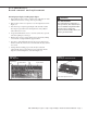
GTS humidifiers: Board removal and replacement Removing Vapor-logic3, installing Vapor-logic4 1. If upgrading an outdoor GTS®, complete Steps 1 through 3 in “GTS with outdoor enclosure” on Page 6 before proceeding. 2. Remove GTS control access panel to access the subpanel, shown in Figure 3-1. 3. Disconnect Vapor-logic3 keypad/display cable and ribbon cables from Vapor-logic3 main board and expansion board(s). Ribbon cables will not be re-used. 4. Torque all terminal block screws to 2.5 in-lb (0.
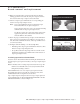
GTS humidifiers: Board removal and replacement 8. Plug Vapor-logic4 keypad/display cable into Display connection on Vapor-logic4 adaptor board (see Figure 4-1). If present, plug laptop or network cable into Ethernet connection on adaptor board. Figure 4-2: Determining LonTalk interoperability VL3 board LonTalk connections (if no wires, then no LonTalk) 9. If upgrading to Vapor-logic4 without LonTalk® interoperability (see Figure 4-2), skip this Step.
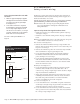
GTS humidifiers: Board removal and replacement 10. Make sure subpanel surface is clean and dry. Remove adhesive backing paper from new stand-offs, and press adaptor board into exact location where Vapor-logic3 board was mounted. Figure 5-1: Splitting interlocked terminal blocks 11. Land loose Vapor-logic3 terminal blocks on corresponding pin locations of Vapor-logic4 adaptor board. Notes: Some 4-pin terminal blocks are two interlocked 2-pin blocks that will need to be split. See Figure 5-1.
GTS humidifiers: Keypad/display removal and replacement Figure 6-1: Keypad/display mounting screws (indoor GTS) Indoor GTS 1. Remove GTS end panel (Figure 6-1) to access keypad/display mounting screws. 2. Remove the four keypad/display mounting screws, and disconnect cable from Vapor-logic3 keypad/display. Vapor-logic3 keypad/ display will not be re-used. 3. Plug cable into Vapor-logic4 keypad/display, position Vapor-logic4 keypad/display over opening, and tighten mounting screws. 4. Replace GTS end panel.
GTS humidifiers: Keypad/display removal and replacement Figure 7-1: VL3 keypad/display, fan, and brackets (outdoor GTS) Remove fan and bracket assembly Remove VL3 keypad/display and bracket assembly GTS04PNLASM-50view Figure 7-2: VL4 keypad/display, fan, and bracket assembly (outdoor GTS) Install VL4 keypad/display, fan, and bracket assembly Mounting screws (use existing holes) GTS04PNLASM-50_testwVL4view DRI-STEEM Vapor-logic3 to Vapor-logic4 Adaptor Board Installation Manual • Page 7
GTS humidifiers: Safety circuit wiring Leave safety circuit wired in series with one alarm 1. Make sure gray-handled jumper supplied with upgrade kit is inserted into terminals P3-3 and P3-4 on Vapor-logic4 adaptor board (Figure 8-1). 2. Locate wire 801 that runs to expansion board terminal T1, and land it at terminal P3-3 on Vapor-logic4 adaptor board. If wire 801 does not reach P3-3, use a longer 18-gauge, stranded wire. Torque terminal block screws to 2.5 in-lb (0.28 N·m).
GTS humidifiers: Safety circuit wiring The following steps are for GTS without door interlock switch: Figure 9-2: Separating safety circuit alarm signals (GTS without door interlock switch) Note: Torque terminal block screws to 2.5 in-lb (0.28 N·m). Torque all other terminal connections to 7 in-lb (0.79 N·m). Blocked flue switch (Figure 9-2) VL3 without interlock VL3door without door interlock 1. Remove wire 414A from position 14 on low water relay.
Electric humidifiers: Board removal and replacement Removing Vapor-logic3, installing Vapor-logic4 WARNING 1. Access humidifier subpanel as follows: Shut down humidifier Before performing any maintenance or service procedures, shut off all electrical power to humidifier using field-installed fused disconnect, and lock all power disconnect switches in OFF position. • Vaporstream and CRUV: Open control cabinet door by loosening the screws on the two door latches.
Electric humidifiers: Board removal and replacement Figure 11-1: Vapor-logic boards VL4 adaptor board (two stacked boards; top board shown) The Vapor-logic4 adapter board pin descriptions are listed in Table 20-1 on the back cover.
Electric humidifiers: Board removal and replacement 9. Make sure subpanel surface is clean and dry. Remove adhesive backing paper from new stand-offs, and press adaptor board into exact location where Vapor-logic3 board was mounted. Figure 12-1: Splitting interlocked terminal blocks 10. Land loose Vapor-logic3 terminal blocks on corresponding pin locations of Vapor-logic4 adaptor board. Notes: Some 4-pin terminal blocks are two interlocked 2-pin blocks that will need to be split. See Figure 12-1.
Electric humidifiers: Keypad/display removal and replacement The Vapor-logic3 keypad/display will not be re-used after this upgrade. Vaporstream and CRUV with mounted keypad/display 1. Push keypad/display straight up to disengage its mounting keyhole slots, and pull it off of mounting plate. 2. Disconnect cable from the Vapor-logic3 keypad/display. 3. Plug cable into new Vapor-logic4 keypad/display, and mount new keypad/display. 4. Close and tightly secure control cabinet door.
Electric humidifiers: Safety circuit wiring • CRUV without door interlock, • Vapormist • Humidi-tech The following procedure leaves the safety circuit (door interlock and low water) wired in series with one alarm: 1. Verify that jumpers shown in Figure 14-1 are in place. 2. Land wire 802 at terminal P3-3 on Vapor-logic4 adaptor board (see Figure 14-1). 3. Humidi-tech only: Clamp ferrite core around drain valve wiring. Proceed to “Start-up and validation” on Page 19.
Electric humidifiers: Safety circuit wiring • CRUV with door interlock • Vaporstream with door interlock • Vaporstream with door interlock and/or cover interlock Figure 15-1: Leaving safety circuit wired in series with one alarm The following procedure leaves the safety circuit (door interlock and low water) wired in series with one alarm: VL3 expansion board (Vaporstream only) 1.
STS humidifiers: Board removal and replacement 1. Access Vapor-logic3 board by loosening screws on the two door latches removing control cabinet door. WARNING Shut down humidifier Before performing any maintenance or service procedures, shut off all electrical power to humidifier using field-installed fused disconnect, lock all power disconnect switches in OFF position. Figure 16-1: VL4 adaptor board stand-offs Stand-off 2. Disconnect Vapor-logic3 keypad/display cable from Vapor-logic3 main board. 3.
STS humidifiers: Board removal and replacement 11. Cut an 18-gauge, stranded wire long enough to reach terminals T2 and 33 on Vapor-logic4 adaptor board (Figure 17-2). Strip ends of wire, land ends at terminals T2 and 33, and torque terminal screws to 2.5 in-lb (0.28 N·m). Figure 17-2: Jumpering terminals T2 and 33 12. Configure either modulating or on-off duct high limit: T2 • Modulating: Move Vapor-logic3 terminal block 24/25/26 to Pins 24/25/26 on Vapor-logic4 adapter board.
STS humidifiers Keypad/display removal and replacement The Vapor-logic3 keypad/display will not be re-used after this upgrade. STS with mounted keypad/display 1. Push keypad/display straight up to disengage its mounting keyhole slots, and pull it off of mounting plate. 2. Disconnect cable from the Vapor-logic3 keypad/display. 3. Plug cable into new Vapor-logic4 keypad/display, and mount new keypad/display. 4. Close and tightly secure control cabinet door. STS with unmounted keypad/display 1.
All Humidifiers: Start-up and validation Start-up See the Start-up commissioning checklist in the humidifier’s Installation, Operation, and Maintenance Manual. Before resuming operation, verify that the current humidifier configuration matches the Vapor-logic4 controller configuration. Refer to the Vapor-logic4 Installation and Operation Manual, and validate every parameter in the Vapor-logic4 Setup menu.
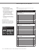
Va p o r- l o g i c 4 a d a p t o r b o a r d pin descriptions For more information www.dristeem.com sales@dristeem.com For the most recent production information visit our Web site: www.dristeem.com Table 20-1 Vapor-logic4 adaptor board pin descriptions Pin # 1, 2 Fill valve 3, 4 Drain valve 5, 6 Power vent (GTS), contactor (electrics) 7, 8 SDU / Area-type fan terminals 9 Fault Relay, N.C. 10 24 Vac, 1 amp max, COM 11 Connected by others, N.O.