Read and save these instructions! VAPOR-LOGIC 3 ® Microprocessor-based humidifier control system Installation and operation manual
PLEASE: read this manual! This manual will guide you through installation, operation and maintenance procedures for your new ® VAPOR-LOGIC 3 microprocessor-based humidifier control system. Proper installation and operating practices will ensure years of trouble-free service. Visit our web site: www.dristeem.com For information about other DRI-STEEM products, visit our web site, or contact us using the information listed below.
Product overview VAPOR-LOGIC 3 features overview. ® Accurate, responsive microprocessor control Our newest controller, VAPOR-LOGIC3, provides unprecedented, comprehensive control for DRI-STEEM humidifiers. With expanded capabilities, easy-to-use keypad, and modular, open protocol design, the VAPOR-LOGIC3 efficiently controls all humidifier functions.
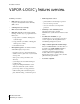
Product overview VAPOR-LOGIC 3 features overview. ® Summary of features • PID control provides the most accurate, responsive and adjustable relative humidity (RH) control. • Self-diagnostic test at start-up • End of season auto-drain • Real-time clock allows time-stamped alarm tracking, and three ways to program drain and flush cycles: 1. Usage (after a set number of lbs/kg have cycled through) 2. Usage and time (set number of lbs/kg plus defined period of time) 3.
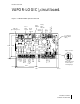
Product overview VAPOR-LOGIC 3 circuit board. ® RJ-11 Cable keypad RJ-45 Cable network Ready water indicator Service indicator Analog output 5/64" dia. (6) mounting holes Power indicator Water level control input Figure 3-1: VAPOR-LOGIC3 printed circuit board To expansion board (ribbon cable) 4.228 3.548 0.312 Analog control inputs Control inputs Control inputs To remote fault indicator (by others) Fill valve Drain valve 0.
Product overview Main control board connections. ® VAPOR-LOGIC 3 main control board connections J1 Wire terminal supplies 24 VAC to power the VAPOR-LOGIC3 control board.
Product overview Main control board connections (cont.). Main control board connections (cont.) Important note about J17, J18 and J19: All connection diagrams show connector shunts on J17, J18 and J19. The connector shunts and appropriate software have been selected by DRI-STEEM based on original customer orders. Field changing the input connector shunts will require control input modification: See Page 23 “Changing Control Input.
Product overview Main control board connections (cont.). Main control board connections (cont.) J23 Wire terminal connection provides optically isolated connection to air flow proving switch and safety circuit. Terminal 12 supplies 24 VAC to proving switch circuit, SPST, which closes when air flow is present. Terminal 13 is the return connection from the proving switch into ® the VAPOR-LOGIC 3 control. Terminal 14 supplies 24 VAC to safety circuit, SPST, which is closed under normal operating conditions.
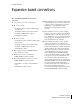
Product overview Expansion board connections.
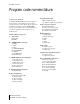
Product overview Program code nomenclature. Program code explained A 14-digit VAPOR-LOGIC®3 program code appears on the front of the control cabinet and on the wiring diagram inside the control cabinet. The program code specifies the parameters of the VAPOR-LOGIC3 microprocessor, which controls your humidification system. An explanation of the program code is detailed below. VAPOR-LOGIC3 program code A. Type of units: E = English M= Metric B.
Product overview Program code nomenclature. Program code example E M 1 1 1 00048 A 7 O O X A. English ® B. VAPORMIST C. One-tank system D. Single keypad E. One heat stage F. 48 lbs/hr capacity G.. Standard water with autodrain H.. TP operating mode I. No VAV option J. No temp comp option K.
Product overview Two-year limited warranty. DRI-STEEM Humidifier Company (“DRI-STEEM”) warrants to the original user that its products will be free from defects in materials and workmanship for a period of two (2) years after installation or twentyseven (27) months from the date DRI-STEEM ships such product, whichever date is the earlier.
Installation Installation checklist. Before installing your VAPOR-LOGIC 3 control system, review this checklist to ensure proper installation of the product. Failure to follow the recommendations listed below could result in failure or damage to the humidifier or microprocessor. Attach the heater/machine ground lug in the junction box, on the humidifier, to the subpanel machine ground lug with the appropriate wire, sized per equipment grounding section of The National Electric Code.
Installation Proper wiring procedures. Proper wiring prevents electrical noise Electrical noise can produce undesirable effects on electronic control circuits, thereby affecting controllability. Electrical noise is generated by electrical equipment, such as inductive loads, electric motors, solenoid coils, welding machinery, or fluorescent light circuits.
Installation Proper wiring procedures (cont.). Proper wiring prevents electrical noise (cont.) • • Do not use chassis or safety grounds as currentcarrying commons. No safety grounds should ever be used as a conductor or neutral to return circuit current.
Installation Control cabinet installation and wiring. ® The VAPOR-LOGIC 3 control board is shipped mounted with all internal wiring completed within a control cabinet. All software has been custom programmed into your VAPOR-LOGIC3 system according to the original order requirements. • VAPOR-LOGIC3 is powered by a low voltage Class 2 control transformer. The transformer provides a 24 VAC supply, and is protected by an integral manual reset circuit breaker.
Installation Keypad/display installation. Installing modular cable Installing the keypad/display IMPORTANT: When routing modular cable inside the control cabinet, route cable away from all power wiring and connect the male modular plug into ® the VAPOR-LOGIC 3 printed circuit board-mounted female modular receptacle, J2. Push male plug in until you hear a “click.” (The cable should be plugged into the keypad/display as well.
Installation Sensing devices and humidity control. 16 Important to properly place sensing devices Other factors that affect humidity control Humidity sensing devices must be properly placed to achieve accurate humidity control. A typical small air handling system is shown in the drawings on Pages 17 and 18 (Figures 17-1 and 18-1). For the best control, place the humidity sensing device in the center of a room, or just inside the return air duct (location “A”).
Installation System Diagram.
Installation Placement of sensing devices. Figure 18-1: Recommended sensor locations A Best B Alternative location C Not recommended D Best duct high limit humidistat High limit humidistat or high limit transmitter (set at 90% RH max.) placement for VAV applications 10' min.
Installation Wiring of sensing devices. Wiring on-off humidistats DRI-STEEM provides three types of on-off controls: wall-mounted humidistat, duct-mounted humidistat, or pneumatic/electric relay. The wiring diagram (found on the inside of the humidifier control cabinet) will show proper wiring for these controls. Wiring modulating humidistats The signal from a humidistat directly controls the amount of output from the humidifier.
Installation Wiring of sensing devices. Figure 20-1: Example of proper shielding techniques when ® connecting humidity or temperature devices to VAPOR-LOGIC 3 control inputs Note: The wiring diagram (found on the inside of the humidifier control cabinet) will show the proper controls wiring. OM-VL3-17 IMPORTANT: Consult control cabinet wiring diagram. Control changes require wiring and programming changes.
Installation Wiring VAV sensing device. Variable air volume (VAV) option This option is identified as a “V” in the third-from-last place of your program code nomenclature (for example: EV11400285A7VOX). When the VAV control option is requested we provide a duct mounted humidity transmitter (4-20 mA output over 0-100% RH range). Install using shielded cable (see Figure 21-1 below).
Installation Temperature compensation transmitter. Temperature compensation offset option This option is identified as a “T” in the second-fromlast place of your program code nomenclature (for example: EV11400285A7OTX). The transmitter provided with VAPOR-LOGIC3 is calibrated for -20°F to 160°F (-29°C to 71°C) with output from 4-20 mA. For example, a temperature reading of 70°F should produce a measurement of 12 mA.
Installation Changing control input. Changing control input 4. Change the last character in the configuration string to the desired input signal type identified from the program coded nomenclature information on Pages 8 and 9. 5. Adjust the shunt connector J17 to the proper signal type, if necessary: ® VAPOR-LOGIC 3 has the ability to accept different types of demand signals from either an energy management system or a humidistat. Follow these steps when a signal change is needed: 1.
Operation Start-up checklist. Note: Your humidification system may not have all of the options listed below. If an item does not appear, skip to the next item and continue the process. Verify that wiring is done per instructions in this manual and the unit wiring diagram. Make sure that the keypad/display is not inside the control cabinet. Check water level control voltages. The reading should be 2.
Operation Start-up checklist (cont.). Confirm that all wiring is correct per the wiring diagram. Confirm that proper grounding and an approved earth ground are provided. Confirm that the J17, J18 and J19 shunt ® connectors on the VAPOR-LOGIC 3 board are in their correct position per the wiring diagram. See Page 3 for the physical locations.
Operation Keypad/display overview. Components of the keypad/display ® The VAPOR-LOGIC 3 keypad/display consists of (see Figure 26-1 below): • • • • A 128 x 64-pixel backlit LCD display A power light An alarm light Eight keys: – Four arrow keys – An Enter key – Three soft keys A soft key’s function is determined by the screen currently displayed. The arrow keys are used to adjust the values of the different parameters of the humidifier. The Enter key is used to make selections on various screens.
Operation VAPOR-LOGIC 3 menu structure.
Operation “Set Up” menu information.
Operation Keypad/display readouts. Readout displayed Description Filling The unit is filling with water. Skimming The unit has completed a fill cycle and is now skimming. Draining The unit is draining. Flushing The unit is flushing. No Duct Air Flow The air flow proving switch is open. Interlock Disable The interlock circuit is open. VAV Output Limit The unit is approaching or has reached the duct RH high limit set point.
Operation Main menu: 1) Status. Status The Status screen is used to view some of the operating parameters of the humidification system.
Operation Main menu: 2) Control Modes. Control Modes In the Control Modes screen, the operational mode of the humidifier can be set. You may choose from auto, test, manual drain or standby. In Auto Mode, the humidifier operates normally. All inputs and outputs are monitored and controlled. If there is a call for humidification, the system will react. In Test Mode, the controller sequentially cycles through all outputs so that their operation may be confirmed.
Operation Main menu: 3) Alarms. Alarms The Alarms screen is used to view the alarm log. Use the vertical arrow keys to scroll through the alarm log. The alarm log contains a record of the previous 10 faults that have occurred on the humidifier. The alarms may either be acknowledged or cleared using the soft keys below the display. If an alarm is acknowledged, it will be cleared and left in the log for future reference. If an alarm is cleared, it will be cleared and removed from the log.
Operation Main menu: 4) Set Up. Set Up In the Set Up screen, the operational parameters of the humidifier can be set.
Operation Main menu: 5) Diagnostics. Diagnostics The Diagnostics screen enables you to troubleshoot some of the hardware input and output points of the ® VAPOR-LOGIC 3 control system. The soft keys Next and Back are used to move through the diagnostic options. Once you have found the item you would like to troubleshoot, view the reading and compare it with what the value should be. For example, if you were going to troubleshoot the RH signal input, you would select RH Signal on the Diagnostics screen.
Operation Main menu: 6) Reports. Reports The Reports screen is useful for viewing historical information about your humidifier. In this section, you are able to view the amount of water that has been used by your humidifier and the amount of energy it has consumed.
Operation Main menu: Idle screen. Idle Screen The Idle screen allows you to monitor the humidifier’s basic operation. Depending on system options, you may view system set point, the actual space condition and the system demand. The top line of the display informs you of the current mode of the humidifier. The second line is a system status line. This line will continuously scroll through any system status items that are currently present.
Operation Control modes. On-off control Demand signal control On-off control is the simplest control scheme, and does exactly what its name implies: the output device turns fully on, then fully off. With demand signal control, the VAPOR-LOGIC3 controller provides the output level that a master control signal calls for. This signal can either be generated by a humidistat or by a building energy management system.
Operation Modulation types: TP modulation. TP modulation The standard form of modulation with an electric humidifier is TP (time-proportioning) modulation. With this type of modulation, the outputs are cycled on and off at a certain rate to approximate humidifier demand.
Operation Modulation types: SSR modulation. There are two basic types of SSR modulation: SSR modulation with contactors, and 100% SSR modulation. SSR modulation with contactors With SSR modulation with contactors, the operation of the unit is the same as it is with TP Modulation. In this scenario, one of the cycling contactors is replaced with an SSR. The SSR is now the device that carries out all of the cycling duties. The contactors will always be either on or off.
Operation Modulation types: valves and burners. ® ® ® STS , LTS and ULTRA-FOG valve modulation With a valve system, the modulation is very simple. The demand signal simply determines how far the valve is going to open. In other words, if the system demand is 25%, the valve will be open 25%. ® GTS burner modulation The burner modulation technique used on a GTS is probably the most complicated. The burners can operate anywhere from 25% to 100% of their capacity.
Operation Control functions: adjusting set point. Adjust set point through Set Up menu Set point adjustments are accomplished through the Set Up menu, which is under the Main Menu (refer to the menu structure diagram on Page 27). Once you have accessed the Set Up menu, you will be able to adjust a number of parameters including the set point of the unit. To adjust the humidity set point, your unit must be configured for a humidity transmitter.
Operation Control functions: PID tuning. Tune your system with PID loop The proportional term When your unit is equipped with a humidity or dew point transmitter (when you are able to adjust the set point through the keypad/display) control is accomplished through a PID control loop. PID stands for Proportional, Integral and Derivative. The proportional band is the band (in % RH, or °F/°C for dew point control) in which the humidifier will modulate.
Operation Control functions: PID tuning (cont.). second the demand is updated. With an integral gain term greater than zero and an actual humidity below set point, each time the demand is updated it is increased slightly. If the actual humidity is above set point, the demand will be decreased slightly. The amount it is increased or decreased is dependent on the difference between the actual humidity and set point. (The closer you are to the set point, the smaller the addition or subtraction.
Operation VAV, temp comp, dew point control. VAV control Dew point control With VAV control, the system is equipped with a duct high limit transmitter. This transmitter sends a signal ® back to the VAPOR-LOGIC 3 controller. The controller then compares the measured duct RH with the high limit set point (Duct High Lim RH) that is entered through the keypad/display in the Set Up screen. As the measured duct RH approaches the high limit set point, the system output is proportionally throttled back.
Operation Aquastat, heat-up, SDU, offsets, metric. Aquastat operation SDU timer The aquastat set point is the minimum tank ® temperature the VAPOR-LOGIC 3 controller should maintain. It is adjusted through the Set Up screen. This feature is typically used to keep the tank from freezing in a cold environment. However, it can also be used to hold a higher minimum temperature if a quick response to a demand signal is needed.
Operation Water level control: conductivity probe. Probe system Standard water systems use a conductivity probe to control water levels for optimum operating efficiency. The three-probe system is monitored by the VAPOR-LOGIC®3 board, which performs all the necessary logic and timing functions to provide total water level control and safety shutdown. VAPOR-LOGIC3 automatically maintains the water level between the upper two probes A and B (see Figures 46-1 and 46-2 below).
Operation Water level control: float valve. Float valve system ® DI/RO water systems (except for ULTRA-FOG ) use a float valve system to control water levels for optimum operating efficiency. DI/RO systems are used where water/steam purity is important, where demineralized water is needed to improve performance or lessen maintenance requirements, or where a potable water source has minimal or no conductivity, thus requiring a float rather than a probe to sense water levels.
Operation Drain and flush, skim. Drain and flush options ® VAPOR-LOGIC 3 is preprogrammed to enter an automatic drain, flush and refill cycle to help keep mineral concentrations in the tank to a minimum. The method by which this is accomplished is selected by the user through the keypad/display in the Set Up screen. The three options available are: 1. Flush after usage 2. Flush at a certain time after usage, and 3.
Operation Service interval, EOS, date set. Setting date and time Service interval ® The VAPOR-LOGIC 3 controller keeps track of how much water has been converted to steam. After a user-defined number of pounds/kilograms have been boiled, a service humidifier message will appear on the keypad/display. However, the humidifier will continue to operate after the message appears. The message is simply to notify the user that the service interval has been reached.
Operation Safety features. Over-temp fault Fill timer ® The VAPOR-LOGIC 3 controller keeps track of approximately how much water, in the form of steam, has left the tank. If this total amount exceeds a preset limit without the fill valve being energized, a low water condition is assumed and the humidifier is shut down. Each time the fill valve is energized, the total is reset to zero. Note that this system is not used on a DI/RO humidifier because the fill valve is not an electricsolenoid type.
Operation Fault messages, diagnostics. Alarms screen Fill and drain faults The Alarms screen on the keypad/display logs the last ten alarms that have occurred on the humidifier. To scroll through the alarms, use the up and down arrow keys. You can acknowledge or clear any one of the alarms using the appropriate soft keys. If an alarm has occurred that you would like to get more information about, highlight that alarm using the arrow keys and then press the Enter key.
Operation Fault messages, diagnostics (cont.). 52 Humidifier faults Sensor meter feature The following is a list of humidifier faults that can occur. Please note that this is a complete list of faults. Your system may not have all of these options. The text in parentheses is what will actually appear in the alarm log. The Diagnostics screen on the keypad/display contains the sensor meter feature.
Operation Reports, multiple tank systems. Energy usage report Multiple tank systems The energy usage report gives an approximate total of how much energy has been consumed by the humidifier since the last service interval. Depending on the system type, this number may be in KWH, MBTU, therms, etc. The VAPOR-LOGIC 3 controller has the ability to be ® connected via a LonTalk network to control up to six tank humidification systems.
Operation Troubleshooting 1, 2, 3. 1. 3. Review troubleshooting index Call us if you’re still having problems If you find that you are having a control-related problem, first check the problem list on the next page. If you are having a tank- or dispersion-related problem, you may also need to refer to those specific product manuals. If the troubleshooting guide does not help you solve your problem, call us with the following information available: 2.
Operation Index to troubleshooting guide. The following is an index to possible control-related problems described on the following pages. To find solutions, refer to either the problem number or the page number shown. # Description 1. 2. 3. Green power indicator light is off .................. Page 56 No remote fault indication ............................. Page 56 No readable information on keypad/display .. Page 56 Faults 4. Humidity transmitter fault .............................. Page 56 5.
Operation Troubleshooting guide. Problem number 1 2 Problem Possible cause Action Green power indicator light is off. No control voltage present Check for proper supply voltage. Heater fuses open Check heater fuses for voltage present at transformer. Transformer secondary circuit breaker tripped Check for wiring shorts; reset breaker. Field wiring not installed Provide field wiring to a remote fault indicator from VAPOR-LOGIC®3 terminal block J22.
Operation Troubleshooting guide. Problem number 6 Problem Possible cause Action Humidistat fault Open, shorted, or incorrect wiring of humidistat Check wiring terminals (VAPOR-LOGIC®3 terminal J26) for correct wiring and voltages. Signal by others is incorrect, out of range, or miswired. Check wiring terminals (VAPOR-LOGIC3 terminal J26) for correct wiring and voltages. Control signal by others has exceeded the range limits. Correct control signal to 0-20 mA, 0-135 ohms, or 0-15 VDC.
Operation Troubleshooting guide. Problem number Problem Possible cause Action 10 Drain fault When in autodrain sequence, end-ofseason, or manual drain, VAPOR-LOGIC®3 allows 20 minutes for the water level to drop from the top probe to below the lowest probe. If the tank does not drain to this level in the time allotted, a fault will be indicated. Check drain valve wiring. Check for voltage present at the valve. If present, clean or replace valve. Check if the tank drain outlet is plugged.
Operation Troubleshooting guide. Problem number Problem Possible cause Action 13 ML probe fault Improper water level changes inside the tank Verify proper wiring of probe system. Clean or replace probe rod assembly. Rewire probes using nonshielded 18gauge wire routed in conduit separate from power wiring. Check that wiring between control cabinet and humidifier does not exceed the recommended 50-foot limit. Check for plumbing problems.
Operation Troubleshooting guide. Problem number Problem Possible cause Action 20 Flue fault The combustion air damper is incorrectly wired or has failed to open. Check for proper combustion air damper wiring. The power vent pressure switch is incorrectly wired or the power vent has failed to start. Check for proper power vent wiring.
Operation Troubleshooting guide. Problem number 24 25 26 Problem Possible cause Slave # fault LonTalk® Connect LonTalk communications communications cable cable. is not connected between boards. Control does not energize. Unit does not fill with water. Action Slave board does not have power or has incorrect power. Verify power wiring on slave board. Nonexistent supply voltage to unit Check main line fuse. Check main line safety switch. Check heater fuses.
Operation Troubleshooting guide. Problem number 26 Problem Possible cause Action Unit does not fill with water (cont.). Unit is not in auto mode. Go to Control Modes screen and select Auto Mode. ® VAPOR-LOGIC 3 control is in end of season drain mode. Check for humidity demand (VAPOR-LOGIC3 control board terminals 21, 22 and 23 of terminal block J26).
Operation Troubleshooting guide. Problem number 27 Problem Fill valve does not close. Possible cause Action Open drain valve If automatic drain valve is locked in manual open position, reset to automatic. Replace valve if there is a broken return spring on the drain valve. Clean or replace drain valve if an obstruction in the valve will not allow complete closure. Close manual drain valve, if it is open. ® If VAPOR-LOGIC 3 shorted output to fill valve coil, replace board.
Operation Troubleshooting guide. Problem number Problem Possible cause Action 27 Fill valve does not close (cont.). Fill valve is stuck Check if fill valve is installed backwards. If yes, repipe. If there is a faulty internal spring or diaphragm in the fill valve, replace valve. Check if there is an obstruction that will not allow valve to seat properly. Clean or replace valve as needed. Check for control voltage across fill valve coil. (Check wiring and controls.
Operation Troubleshooting guide. Problem number 29 30 Problem Possible cause Action Fill valve cycles on and Malfunctioning level off frequently (several control system times per minute). If needed, clean probe tips. Check water conductivity. (Minimum conductivity for proper operation of level control system is 100 micromhos per centimeter or 2 grains per gallon.) Verify that probe wiring is correct.
Operation Troubleshooting guide. Problem number 31 Problem Noisy operation Possible cause Action Thunder-type noise coming from tank during refill Normal on larger units, caused by the cold fill water collapsing steam in the tank. Reduce psi (minimum of 25 psi) if inlet water pressure is too high. Contactor noise Contactor normally makes a clunk as it pulls in. A continuous chattering noise is not normal and is symptomatic of a failing contactor or malfunctioning controls.
Operation Troubleshooting guide. Problem number 32 Problem Possible cause Action Humidity below desired level Unit operating but fails to meet required humidity output Unit undersized; replace with a larger unit or add additional humidifier. Skimmer rate is too high. If drain valve will not close fully, determine the cause and clean, repair or replace as needed. If drain pipe water seal is allowing steam to go down the drain, repair as needed.
Operation Troubleshooting guide. Problem number 32 33 Problem Possible cause Action Humidity below desired level (cont.) Heating elements not operating If heaters are burned out, refer to Problem #30 Heater burnout. Verify that humidistat is calling for humidity. Check for control voltage if limit controls (air flow proving switch, zone valves, etc.) are not allowing unit to operate. Check fuses and replace if they are blown.
Operation Troubleshooting guide. Problem number Problem Possible cause Action 33 Humidity above set point (cont.) Malfunctioning controls 34 Hunting (humidity swings above and below desired set point) Malfunctioning control system If there is a faulty or inaccurate humidity controller or transmitter, repair or replace. Check for proper VAPOR-LOGIC®3 control settings: RH set point, HL set point, cycle rate, PID tuning, etc. Relocate poorly located control components.
Operation Troubleshooting guide. Problem number 35 Problem Possible cause Action Unit does not perform autodrain sequence. System may not have automatic drain system Inspect unit to verify that automatic drain valve was furnished. Drain fault, plugged Clean drain valve piping. drain valve or plugged drain pipe 70 Operation: Troubleshooting guide Malfunctioning autodrain sequence Check VAPOR-LOGIC®3 main menu settings and reset if necessary.
71
72
14949 Technology Drive • Eden Prairie, MN 55344 Phone: (612) 949-2415 • Fax: (612) 949-2933 E-Mail: sales@dristeem.com • Web: www.dristeem.com European Office: Bell Place, Bell Lane • Syresham, Brackley • NN13 5HP, U.K. Phone: +44 1280 850122 • Fax: +44 1280 850124 E-Mail: 106277.1443@compuserve.com Printed on recycled paper. Printed on recycled paper with agribased inks Minimum 10% Post Consumer Waste.