Va p o r m is t ® E le ctric H umidifie r Ins tal l ati o n, Op eration and Mai ntenance Man u al
ATTENTION INSTALLER Read this manual before installing. Leave manual with product owner. DRI-STEEM® technical support WARNING! Disconnect electrical power before installing supply wiring. Contact with energized circuits can cause severe personal injury or death as a result of electrical shock. 800-328-4447 This product must be installed by qualified HVAC and electrical contractors and in compliance with local, state, federal, and governing codes.
5B C M F P G D P O U F O U T Product overview Product overview . . . . . . . . . . . . . . . . . . . . . . . . . . . . . . . . . . . . . . . 2 Electrical specifications, capacities and weights . . . . . . . . . . . . . 4 Dimensions . . . . . . . . . . . . . . . . . . . . . . . . . . . . . . . . . . . . . . . . . . . . 5 Installation Choosing a location for the humidifier. . . . . . . . . . . . . . . . . . . . . 6 Mounting the humidifier . . . . . . . . . . . . . . . . . . . . . . . . . . . . . . . .
1SPEVDU PWFSWJFX Note: See Pages 8 and 9 for detailed installation drawings.
1SPEVDU PWFSWJFX DPOUJOVFE Dispersion assembly options In addition to single tube dispersion, shown in Figure 2-3, the dispersion options shown on this page are available for Vapormist humidifiers. See pages 14-30 for installation instructions. Figure 3-3: SDU-E Figure 3-1: Ultra-sorb® dispersion Space Distribution Unit (SDU) shown mounted directly above a Vapormist humidifier OM-55-1 OM-636-1 Figure 3-4: SDU mounted remotely Figure 3-2: Rapid-sorb® dispersion OM-56-1 OM-637-1 %3* 45&&.
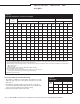
4 Q F D J G J D B U J P O T D B Q B D J U J F T B O E XFJHIUT Table 4-1: Vapormist specifications, capacities, and weights Model Current draw (amps) Maximum steam capacity Single-phase Weights ‡ Three-phase Shipping Operating kW lbs/hr kg/h 120V 208V* 240V* 480† 600V† 208V* 240V† 480V† 600V† lbs kg lbs kg 2 6 2.7 16.7 9.6 8.3 4.2 3.3 — — — — 80 36 95 43 4 12 5.4 33.3 19.2 16.7 8.3 6.7 16.7** 14.4** 7.2** 5.8** 80 36 95 43 6 18 8.2 — 28.8 25.
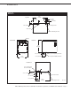
%JNFOTJPOT Figure 5-1: Dimensions 24.2" (614 mm) Top view 2" (50 mm) 10.9" (276 mm) 2" (50 mm) 1" (25 mm) 2.25" (57 mm) Power wiring knockout Steam outlet Control or SDU wiring knockout Venting Front view Left side view 18.6" (472 mm) 1.50" (38 mm) 2.25" (57 mm) ¾" pipe thread (DN20) frame drain 5.75" (146 mm) 16.1" (409 mm) ¾" pipe thread (DN20) tank drain Bottom view 0.50" (13 mm) hole in base for water fill line 0.75" (19 mm) 0.63" (16 mm) 2.25" (57 mm) Power wire knockout 1.
$ I P P T J O H B M P D B U J P O Choosing a location for the humidifier When selecting a location for the humidifier, consider the following: t Proximity to duct Install the humidifier near the air duct system where the dispersion assembly will be located. The maximum recommended length for vapor hose connecting a single humidifier to a dispersion assembly is 10' (3 m). The maximum recommended developed length for tubing or pipe connecting a single humidifier to a dispersion assembly is 20' (6 m).
.PVOUJOH UIF IVNJEJGJFS Mounting the humidifier on the wall When mounting on a wood stud wall (studs 16" [406 mm] on center), locate studs and position lag bolts in place so that each of the bolts centers on a stud. Mark hole locations and predrill ¼" (6 mm) diameter pilot holes. Secure cabinet to wall with lag bolts provided. When mounting on a metal stud wall, locate the studs (16" [406 mm] on center) and drill a 3/8" (10 mm) hole through the studs and wall.
7B Q P S N J T U Q J Q J O H T U B O E B S E X B U F S NPEFMT Figure 8-1: Vapormist (standard water models) field piping overview Water supply line; water pressure must be between 25 psi and 80 psi (175 kPa and 550 kPa); water conductivity minimum 100 μS/cm. If water piping to humidifier is nonmetallic, we recommend that the first 3' (1 m) of water supply piping from the humidifier be metallic Steam vapor hose; may also use pipe or tubing.
7B Q P S N J T U Q J Q J O H % * 3 0 X B U F S NPEFMT Figure 9-1: Vapormist-DI (deionized/reverse osmosis water models) field piping overview Steam vapor hose; may also use pipe or tubing. See Table 16-1 for maximum piping lengths.
4VQQMZ XBUFS BOE ESBJO QJQJOH Supply water and drain piping WARNING! Opening the drain valve when the tank is hot can discharge water with a temperature up to 212 °F (60 °C) into the plumbing system. This can cause damage to the plumbing system if the humidifier is not properly connected to a water tempering device such as a DRI-STEEM Drane-kooler™ . Do not touch the tank or drain piping until the unit has had sufficient time to cool, or serious injury can occur.
7B Q P S N J T U X J S J O H Humidifier field wiring All wiring must be in accordance with all governing codes, and with the humidifier wiring diagrams. The diagrams are located inside the removable subpanel cover on the right side of the humidifier cabinet. Power supply wiring must be rated for 105 °C. When selecting a location for installing the Vapormist, avoid areas close to sources of electromagnetic emissions such as power distribution transformers.
7B Q P S N J T U X J S J O H D P O U J O V F E Figure 12-1: Shielded/screened cable drain wire connection to lug WARNING! DRI-STEEM strongly recommends installing a duct airflow proving switch and a duct high limit humidistat. These devices prevent a humidifier from making steam when there is low airflow in the duct or when the RH level in the duct is too high.
) V N J E J T U B U B O E U S B O T N J U U F S QMBDFNFOU Humidistat and transmitter locations are critical Humidistat or transmitter location has a significant impact on humidifier performance. In most cases, it is recommended that you do not interchange duct and room humidity devices. Room humidity devices are calibrated with zero or little airflow; whereas duct humidity devices require air passing across them.
% J T Q F S T J P O (FOFSBM JOTUSVDUJPOT Four places to find more information about dispersion 1. In this document: t *OUFSDPOOFDUJOH QJQJOH BOE ESJQ UFF installation, pages 15-17 t 4%6 * BOE 4%6 & TQBDF EJTUSJCVUJPO units) information, pages 18-21 t 4JOHMF UVCF JOTUBMMBUJPO JOTUSVDUJPOT pages 22-23 t 3BQJE TPSC® installation instructions, pages 24-30 2. On our web site: The following documents can be viewed, printed, or ordered from our web site, www.dristeem.
% J T Q F S T J P O * O U F S D P O O F D U J O H Q J Q J O H SFRVJSFNFOUT Connecting humidifier to dispersion assembly with vapor hose Important: t "MXBZT TVQQPSU WBQPS IPTF UP QSFWFOU TBHT PS MPX TQPUT BOE UP maintain a minimum pitch of 2"/ft (15%) back to the humidifier. t 4FF UIF NBYJNVN TUFBN DBSSZJOH DBQBDJUZ UBCMF PO UIF OFYU QBHF t 6TF %3* 45&&.
% J T Q F S T J P O * O U F S D P O O F D U J O H Q J Q J O H SFRVJSFNFOUT DPOUJOVFE Connecting humidifier to dispersion assembly with tubing or pipe (continued) t *OTVMBUJOH IBSE QJQF SFEVDFT UIF MPTT JO PVUQVU DBVTFE CZ condensation. t 8IFO VTJOH IBSE QJQF UBLF DBSF UP SFNPWF "-- USBDFT PG lubricants used to thread the pipe. This will minimize the possibility of tank foaming. Denatured alcohol or mineral spirits work best for removing lubricant.
%JTQFSTJPO %SJQ UFF JOTUBMMBUJPO Drip tee installation WARNING! Install a drip tee as shown below when the humidifier is mounted higher than the dispersion assembly, when interconnecting hose or piping needs to go over an obstruction, or when interconnecting piping runs are long. Dispersion tube, vapor hose, tubing, or hard pipe can contain steam, and surfaces can be hot. Discharged steam is not visible.
%JTQFSTJPO 4%6 * BOE 4%6 & SDU-I: Provides instant, internal absorption Figure 18-1: SDU mounted directly above the Vapormist Steam outlet Air intake vents The Space Distribution Unit Internal Absorption (SDU-I) disperses humidity with no visible vapor trail or wetness, making the Vapormist with an SDU-I ideal for use in finished spaces. When room RH is 45% or less, the SDU-I fan mixes room air and steam to ensure complete absorption before discharge as humidified air.
%JTQFSTJPO 4%6 * BOE 4%6 & DPOUJOVFE Installing Space Distribution Units (SDUs) Provide at least 6" (150 mm) clearance on each side of the SDU. Field wiring is required to connect the SDU fan and airflow proving switch terminals to Vapormist electrical panel terminals. Refer to the external connections diagram in the package shipped with your unit. Table 19-1: SDU specifications SDU-I SDU-E Amps at 120V (50/60 Hz) 3.20 2.07 Horsepower 1/5 1/8 Airflow cfm 760 545 m3/s 0.36 0.
%JTQFSTJPO 4%6 * BOE 4%6 & DPOUJOVFE WARNING! If standing water is allowed to accumulate in the dispersion box: t *U DBO DBVTF CBDUFSJB BOE NPME HSPXUI which can cause illness. t *U DBO BGGFDU 4%6 & GBO VOJU QFSGPSNBODF and can cause hot water at 212 °F (100 °C) to discharge from the SDU-E fan unit, which can cause severe personal injury. Condensate drain connection to SDU-E fan unit 1. Piping must be minimum ¾" I.D.
% J T Q F S T J P O 4 % 6 & S J T F U I S P X B O E TQSFBE As steam is discharged from the SDU-E, it quickly cools and turns to a visible fog that is lighter than air. As this fog is carried away from the SDU-E by the airstream, it tends to rise toward the ceiling. If this fog contacts solid surfaces (columns, beams, ceiling, pipes, etc.) before it disappears, it could collect and drip as water. The greater the space relative humidity, the more the fog will rise, throw and spread.
%JTQFSTJPO 4JOHMF UVCF Figure 22-1: Single tube without condensate drain Duct Single dispersion tube without condensate drain Vapor hose, tubing or pipe. Insulate tubing and hard pipe to reduce steam loss. Do not insulate vapor hose. See Table 16-1 for maximum piping lengths. Secure and seal escutcheon plates Vapormist humidifier VM 2-8 A Dimension A: t NN GPS UVCFT t NN GPS UVCFT A See the first bullet in the notes below.
%JTQFSTJPO 4JOHMF UVCF DPOUJOVFE Figure 23-1: Single tube with condensate drain Vapor hose, tubing or pipe. Insulate tubing and hard pipe to reduce steam loss. Do not insulate vapor hose. See Table 16-1 for maximum piping lengths. 90° long sweep or two 45° elbows See the first bullet in the notes below. Vapormist humidifier Notes: 1. Pitch vapor hose, tubing or pipe toward humidifier: – 2"/ft (15%) when using vapor hose – ½"/ft (5%) when using 1½" tubing or pipe – ¼"/ft (2%) when using 2" tubing or pipe 2.
%JTQFSTJPO 3BQJE TPSC Important: General Rapid-sorb installation instructions Failure to follow the recommendations in this section can result in excessive back pressures on the humidifier. This will result in unacceptable humidification system performance such as leaking gaskets, blown water seals, erratic water level control, and spitting condensate from the dispersion tube(s). t #FGPSF ZPV CFHJO JOTUBMMBUJPO SFBE BMM EJTQFSTJPO JOTUSVDUJPOT JO this manual.
%JTQFSTJPO 3BQJE TPSC DPOUJOVFE Rapid-sorb pitch requirements t 8IFO JOTUBMMJOH B 3BQJE TPSC XJUI UIF IFBEFS PVUTJEF B horizontal airflow duct, consider the following pitch issues: – For 1½" (DN40) dispersion tubes use a fastener of sufficient length to accommodate the 1/8"/ft (1%) pitch requirements toward the ¾" pipe thread (DN20) header drain fitting. – For 2" (DN50) dispersion tubes, the bracket can be mounted flush to the ductwork.
%JTQFSTJPO 3BQJE TPSC DPOUJOVFE Figure 26-1: Rapid-sorb dispersion assembly Position L-bracket so that flange is upstream of dispersion tubes. Drawing shows L-bracket positioned for airflow back to front.
%JTQFSTJPO 3BQJE TPSC DPOUJOVFE Fasten the L-bracket to the end of the dispersion tubes with the provided bolt, lock washer, and flat washer. 5. Before tightening the L-bracket bolts to the dispersion tubes follow these instructions: t 'PS %/ EJTQFSTJPO UVCFT – The dispersion tube will rotate in the slip coupling. Verify that the dispersion tube orifices are directed perpendicular to the airflow.
%JTQFSTJPO 3BQJE TPSC DPOUJOVFE Figure 28-1: Rapid-sorb installed in a horizontal airflow with header inside the duct Position L-bracket so that flange is upstream of dispersion tubes. This drawing shows the L-bracket positioned for airflow back to front Dispersion tube flow Air Point tubelets (steam orifices) perpendicular to airflow Duct Slip coupling or hose cuff 90° long sweep or two 45° elbows Vapor hose, tubing or pipe. Insulate tubing and hard pipe to reduce steam loss. Do not insulate vapor hose.
%JTQFSTJPO 3BQJE TPSC DPOUJOVFE t 3PUBUF UIF TMJQ DPVQMJOH BT ZPV QVTI JU PO UP UIF UVCJOH t 5IF 0 SJOHT BSF MVCSJDBUFE BU UIF GBDUPSZ *G BEEJUJPOBM lubrication is necessary, DO NOT use a petroleum-based lubricant. 5. Allow the dispersion tubes to rest against the bottom of the duct. 6. Position the flange of the L-bracket so it is upstream of the tubes when the assembly is rotated into position.
%JTQFSTJPO 3BQJE TPSC DPOUJOVFE Steam supply connections to the Rapid-sorb header 1. Connect the steam supply interconnecting piping from the humidifier to the Rapid-sorb. The steam supply piping requires a minimum of 1/8"/ft (1%) pitch toward the header. 2. If multiple humidifiers are supplying one Rapid-sorb, a multiple steam supply connector is provided. t 5ZQJDBMMZ UIF NVMUJQMF TUFBN TVQQMZ DPOOFDUPS BUUBDIFT UP UIF Rapid-sorb header supply end with hose cuff and clamps.
)VNJEJGJFS TUBSU VQ QSPDFEVSF After the system is installed and connected properly, you can begin start-up procedures. 1.
. B J O U F O B O D F 7B Q P S N J T U T U B O E B S E XBUFS NPEFMT WARNING! Do not remove the humidifier electrical panel cover or the heater terminal cover until electrical power is disconnected. Contact with energized circuits can cause property damage, severe personal injury or death as a result of electrical shock.
. B J O U F O B O D F 7B Q P S N J T U T U B O E B S E XBUFS NPEFMT DPOUJOVFE Cool down humidifier before beginning maintenance Before performing any maintenance, allow the tank to cool down. Note: Fresh make-up water is used to speed up cooling. Do not close the manual water supply before cooling down the humidifier; otherwise the tank could stay hot for several hours.
. B J O U F O B O D F 7B Q P S N J T U T U B O E B S E XBUFS NPEFMT DPOUJOVFE 4FBTPOBMMZ (or as required, depending on water quality) t 3FNPWF UIF FWBQPSBUJOH DIBNCFS – Remove the two fasteners on each side of the cover enclosure (see figure below) – Remove the enclosure. WARNING! Do not remove the humidifier electrical panel cover or the heater terminal cover until electrical power is disconnected.
. B J O U F O B O D F 7B Q P S N J T U T U B O E B S E XBUFS NPEFMT DPOUJOVFE t *OTUBMM UIF QSPCF BOE QSPCF QMVH BTTFNCMZ 7FSJGZ HSPVOE XJSF is solidly connected to tank. t 4FDVSF UIF DIBNCFS DPWFS NBLJOH TVSF UIF DPWFS HBTLFU JT seated and the chamber is sealed. t 3F JOTUBMM UIF FWBQPSBUJOH DIBNCFS – Reconnect the fill line. – Reconnect the electrical plugs (plugs are color coded). – Reconnect the drain union. – Reconnect the vapor hose.
. B J O U F O B O D F 7B Q P S N J T U % * 3 0 XBUFS NPEFMT WARNING! Do not remove the humidifier electrical panel cover or the heater terminal cover until electrical power is disconnected. Contact with energized circuits can cause property damage, severe personal injury or death as a result of electrical shock or fire. Only qualified electrical personnel should perform start-up procedure. DI water models (Vapormist-DI) Vapormist DI models use DI/RO water.
. B J O U F O B O D F 7B Q P S N J T U % * 3 0 XBUFS NPEFMT DPOUJOVFE 2. Loosen the four cover bolts and remove the cover assembly from the tank. 3. Inspect the tank interior for debris or pitting. 4. Inspect the valve inlet for debris. 5. Check the operation of the float valve and the condition of the float seat. 6. Check the low water switch to make sure the float slides freely on the stem. 7. Secure the chamber cover making sure the cover gasket is seated and the chamber is sealed. 8.
3FQMBDFNFOU QBSUT Figure 38-1: Humidifier replacement parts Vapormist standard water model Vapormist-DI water model Note: Refer to the table on the next page for replacement part numbers. OM-768 1BHF t %3* 45&&. 7BQPSNJTU &MFDUSJD )VNJEJGJFS *OTUBMMBUJPO 0QFSBUJPO BOE .BJOUFOBODF .
3FQMBDFNFOU QBSUT DPOUJOVFE Table 39-1: Replacement parts (refer to drawing on Page 36) No. Description Qty. Part no. No. Description Qty. Part no.
3FQMBDFNFOU QBSUT DPOUJOVFE Figure 40-1: Space distribution unit, external absorption (SDU-E) OM-1503 Table 40-1: SDU-E replacement parts No. Description Qty.
3FQMBDFNFOU QBSUT DPOUJOVFE Figure 41-1: Space distribution unit, internal absorption (SDU-I) OM-1504 Table 41-1: SDU-I replacement parts No. Description Qty. Part number 1 Shroud 1 330001-002 2 Blower, SDU99 external assembly 1 * 3 Switch, airflow 1 406190 4 Screw, 8-32 × 1½" PHMS Phillips 6 700170-007 5 Nut retainer, 8-32 6 409593-001 6 Cap, black 6 409593-002 7 Tubelet, 0.375" × 0.375" molded 44 310280-006 Notes: * This is an assembly of multiple parts.
3FQMBDFNFOU QBSUT DPOUJOVFE Figure 42-1: Vapormist subpanel with SSR OM-213-4 Table 42-1: Subpanel replacement parts No. 1 Description Qty. Part number No. Description Qty. Part number Subpanel, VM99 barrier 1 120801 9 Main board, VL3 1 408491-x.x.xM** DIN rail, 8" long 1 167765-008 10 Display board, VL3 1 408491-x.x.xD** DIN rail, 10.
3FQMBDFNFOU QBSUT DPOUJOVFE Table 43-1: Subpanel replacement parts Figure 43-1: Vapormist subpanel with SDU No. Qty.
/PUFT 1BHF t %3* 45&&. 7BQPSNJTU &MFDUSJD )VNJEJGJFS *OTUBMMBUJPO 0QFSBUJPO BOE .BJOUFOBODF .
/PUFT %3* 45&&. 7BQPSNJTU &MFDUSJD )VNJEJGJFS *OTUBMMBUJPO 0QFSBUJPO BOE .BJOUFOBODF .
Expect quality from the industry leader Two-year Limited Warranty For over 40 years, DRI-STEEM has been leading the industry with creative and reliable humidification solutions. Our focus on quality is evident in the construction of this humidifier, which features cleanable, stainless steel construction, and an industry-leading Two-year Limited Warranty.