
Data Sheet

© Copyright by Drive-System Europe Ltd. Stand: 18.04.2018
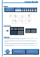
Dimensions
Linear actuator
Length
Size
in mm
Stroke ± 3mm
50 100 150 200 250 300 350 400
DSZY35 - Version HS2
A
retracted
237 287 337 387 437 487 537 587
B
extended
287 387 487 587 687 787 887 987
Terminal assignment
red black Move
M+ M- extends
M- M+ retracts
withe
COM
blue
Data1
green
Data2
yellow
Vcc
Gear reduction pulse / mm
I=19 9,56
I=27 13,5
I=43 21,45
Installation notes
Attention: The DSZY35 has no integrated limit switches. In general, we recommend, that you also set separate limit switches. This prevents
that the cylinder does not drive into its mechanical end positions and the motor burns out..
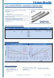
Please make sure, that load is not bigger than shown in the diagram speed/load. If overload is possible in the application, please use a
separate current control to switch off at too high current ( = too high load ). Nominal current, depending on ratio, is shown in the diagram
current / load.
Please use the right voltage supply as it is shown on the actuator. For extending the piston rod connect the red cable with plus and the black
cable with minus. For moving back, reverse the polarity (change plus and minus). Endswitches are not adjustable by themselves.
Load should be centered in moving direction and transverse forces should be avoid because of shortening the lifetime. Big transverse forces
can destroy the actuator! Be carefull.
Drive-System Europe Ltd.
www.drive-system.com
engineering@drive-system.com