Delta 1000 Ultra Light Plus, Full Electric Low Bed Item # 15235 Owner’s Assembly And Operating Manual
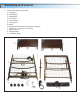
Assembly Instructions 1. Confirm that all parts are present. A. Foot Spring B. Head Spring C. Head Board D. Foot Board E. Hi/Low Shaft F. Locking Pins G. Motor H. Hand Crank (attached to foot board for shipping) I. Casters (4) - 2 locking, 2 non-locking J. Spring Clips (2) K. Hand Pendant L.
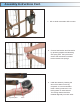
Assembly Instructions Cont. 2. Connect the head spring by aligning with foot spring and swinging both ends away from each other. 3. Optional: Insert lock pin through connected sleep surface and secure with spring clip.
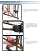
Assembly Instructions Cont. 4. Place the foot spring standing up on the floor on its side. Slide Hi/Low shaft through hanger bracket. Hanger Bracket 5. Install Hi/Low shaft to the Hi/Low motor at the foot section of the bed by inserting the spring loaded side of the shaft to the bottom receptacle as shown. Spring Loaded Shaft Thumb Screw 6. Slide lock collar 1/4” from the foot side of the hanger bracket as shown. Tighten thumb screw.
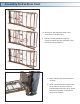
Assembly Instructions Cont. 7. Hi/Low shaft connected to Hi/Low motor. 8. Connect head section and foot section by squeezing together and attaching with spring links. Pull up the head section and foot section to release tension between the springs. 9. Install the casters by inserting the stem of the caster into the leg receptacle. It is recommended to install 1 locking caster and 1 nonlocking caster on each bed end. The locking casters should be installed diagonally from each other.
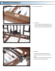
Assembly Instructions Cont. 10. With bed on side extend the shaft until it reaches the full length of bed. a. NOTE: The shaft adjustment holes are marked to indicate the style (semi/full) of bed the shaft is being installed on. 11. Attach the head board and foot board as shown. a. NOTE: The head section is higher than the foot section. However, they are interchangeable with each other, with all other Drive and other manufacturers head and foot boards.
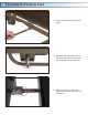
Assembly Instructions Cont. 12. Install the head end of the shaft as shown. 13. Release the spring loaded shaft on the hi/low motor and insert the shaft into the gear box on the footboard. 14. Make sure the slot on the spring loaded shaft engages the roll pin on the gear box.
Motor Installation NOTE: Before installing motor, plug hand pendant and Hi/Low motor cable into motor as shown 14. Connect the 9V battery (sold separately) to the battery clip on the motor. It is stored in the recess under the motor cover. With this battery installed, the motor can be operated in the event of a power failure. 15. To install motor, remove locking caps on top of the motor.
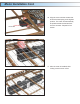
Motor Installation Cont. Actuator Bar 16. Align the motor with the actuator bar and lift the head spring to the highest position. The motor will automatically be pulled towards the bed and lock onto the accuator. Repeat for foot section. 17. After the motor is installed, slide locking covers back on motor.
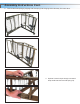
Bed Rail Installation 18. Attaching Bed Rails a. Half rails • The head section features labels on the frame marked, “Attach Half Rails Here” and black springs for proper placement. b. Full Rails • • The foot and head section have color coded springs, labels and notches in the frame. Install the cross brace between the black springs for proper rail placement.
Mattress Installation 20. Before a mattress is laid on the bed, flip up the mattress guard to reduce the movement of the mattress. Maintenance & Safety Checks Drive recommends the following maintenance and cleaning procedures be conducted between users. ELECTRONICS • Check all controls to make sure all functions work properly. • Foot control • Head control • Hi/Lo • Check all cables for damaged or frayed wires. • Power cord • Pendant cord • Check to make sure all plugs are fully inserted or attached.
99 Seaview Boulevard Port Washington, NY 11050 Phone: 516-998-4600 Toll Free: 877.224.0946 Fax: 516.998.4601 www.drivemedical.