Installation and Operation Manual Baltic II (DB03041 model) US ENVIRONMENTAL PROTECTION AGENCY PHASE II CERTIFIED WOOD STOVE Safety tested according to ULC S627 and UL 1482 Standards by an accredited laboratory www.drolet.ca Stove Builder International Inc. 250, rue de Copenhague, St-Augustin-de-Desmaures (Quebec) Canada G3A 2H3 After-sale service: 418-908-8002 E-mail: tech@sbi-international.com This manual is available for free download on the manufacturer’s web site. It is a copyrighted document.
Baltic II Installation and Operation Manual THANK YOU FOR CHOOSING THIS DROLET WOOD STOVE As one of North America’s largest and most respected wood stove and fireplace manufacturers, Stove Builder International takes pride in the quality and performance of all its products. We want to help you get maximum satisfaction as you use this product.
Baltic II Installation and Operation Manual Table of content PART A - OPERATION AND MAINTENANCE ...............................6 1 Safety Information .....................................................................6 1.1 Summary of Operation and Maintenance Cautions and Warnings ......................... 6 2 General Information on Baltic II (DB03041) .............................7 2.1 Appliance performance(1) ....................................................................................... 7 2.
Baltic II Installation and Operation Manual 5 Maintaining Your Wood Heating System ...............................23 5.1 Stove Maintenance............................................................................................... 23 5.1.1 Plated Finish Maintenance ................................................................................ 23 5.1.2 Cleaning Door Glass ......................................................................................... 23 5.1.3 Door adjustment .................
Baltic II Installation and Operation Manual 8.6.1 Installation of Single Wall Chimney Connector ................................................. 42 Appendix 1: Top Bricks Installation ............................................45 Appendix 2: Installation of the Bypass Damper Handle Holder ...................................................................................46 Appendix 3: Installing the Optional Fresh Air Intake kit (AC01336).................................................................
Baltic II Installation and Operation Manual PART A - OPERATION AND MAINTENANCE Please see Part B for installation instructions. 1 Safety Information 1.1 Summary of Operation and Maintenance Cautions and Warnings • HOT WHILE IN OPERATION, KEEP CHILDREN, CLOTHING AND FURNITURE AWAY. CONTACT MAY CAUSE SKIN BURNS. GLOVES MAY BE NEEDED FOR STOVE AND BYPASS DAMPER OPERATION.
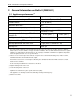
Baltic II Installation and Operation Manual 2 General Information on Baltic II (DB03041) 2.1 Appliance performance(1) Fuel type Recommended heating area Dry cordwood [*] 900 to 2,100 ft2 (84 to 195 m2) Firebox volume 3.4 ft3 (0.096 m3) Maximum burn time[*] 10 h Maximum heat output (dry cordwood) 90,000 BTU/h 11,700 BTU/h to 26,400 BTU/h (3.4 kW to 7.7 kW) Overall heat output rate (min. to max.
Baltic II Installation and Operation Manual 2.
Baltic II Installation and Operation Manual 9
Baltic II Installation and Operation Manual 2.3 Zone Heating and How to Make it Work for You Your new Baltic II wood stove is a space heater, which means it is intended to heat the area it is installed in, as well as spaces that connect to that area, although to a lower temperature. This is called zone heating and it is an increasingly popular way to heat homes or spaces within homes.
Baltic II Installation and Operation Manual 2.4 The Benefits of Low Emissions and High Efficiency The low smoke emissions produced by the special features inside the Baltic II firebox mean that your household will release up to 90 percent less smoke into the outside environment than if you used an older conventional stove. But there is more to the emission control technologies than protecting the environment.
Baltic II Installation and Operation Manual 3 Fuel 3.1 Materials That Should Not be Burned • GARBAGE OF ANY KIND, • COAL OR CHARCOAL, • TREATED, PAINTED OR COATED WOOD, • PLYWOOD OR PARTICLE BOARD, • FINE PAPER, COLORED PAPER OR CARDBOARD, • SALT WATER DRIFTWOOD, • MANUFACTURED LOGS CONTAINING WAX OR CHEMICAL ADDITIVES, • RAILROAD TIES, • LIQUIDS SUCH AS KEROSCENE OR DIESEL FUEL TO START A FIRE. 3.2 How to Prepare or Buy Good Firewood 3.2.
Baltic II Installation and Operation Manual 3.2.3 Log Length Logs should be cut about 1” (25 mm) shorter than the firebox so they fit in easily. Pieces that are even slightly too long make loading the stove very difficult. The most common standard length of firewood is 16” (400 mm). The pieces should be a consistent length, with a maximum of 1” (25 mm) variation from piece to piece. 3.2.4 Piece Size Firewood dries more quickly when it is split. Large unsplit rounds can take years to dry enough to burn.
Baltic II Installation and Operation Manual 3.2.5 How to Dry Firewood Firewood that is not dry enough to burn is the cause of most complaints about wood inserts. Continually burning green or unseasoned wood produces more creosote and involves lack of heat and dirty glass door. See Section 5: Maintaining your wood heating system for concerns about creosote.
Baltic II Installation and Operation Manual 3.2.
Baltic II Installation and Operation Manual 4 Operating Your Stove 4.1 Your First Fires Two things will happen as you burn your first few fires; the paint cures and the internal components of the stove are conditioned. As the paint cures, some of the chemicals vaporize. The vapors are not poisonous, but they do smell bad. Fresh paint fumes can also cause false alarms in smoke detectors. So, when you first light your stove, be prepared by opening doors and/or windows to ventilate the house.
Baltic II Installation and Operation Manual After the kindling fire has mostly burned, you can add standard firewood pieces until you have a fire of the right size for the conditions. 4.2.2 The Top Down Fire The top down fire starting method solves two problems with the conventional method: first, it does not collapse and smother itself as it burns; and second, it is not necessary to build up the fire gradually because the firebox is loaded before the fire is lit.
Baltic II Installation and Operation Manual Wood burns best in cycles. A cycle starts when a new load of wood is ignited by hot coals and ends when that load has been consumed down to a bed of charcoal about the same size as it was when the wood was loaded. Do not attempt to produce a steady heat output by placing a single log on the fire at regular intervals.
Baltic II Installation and Operation Manual Remove ash first, and then rake charcoal towards the front of the firebox before loading so that it will ignite the new load. 4.3.4 Firing Each New Load Hot Place the new load of wood on and behind the charcoal, and not too close to the glass. Close the door and open the air control fully. Leave the air control fully open until the firebox is full of flames, the wood has charred to black and its edges are glowing red.
Baltic II Installation and Operation Manual If the flames get small and almost disappear when you turn down the air, you have turned down the air too early, or your firewood is wetter than it should be. With good fuel and correct air control use, the flames should slow down, but should stay large and steady, even as the air supply is reduced. 4.3.6 Use of the bypass damper Your stove is equipped with a bypass damper.
Baltic II Installation and Operation Manual CAUTION: NEVER LEAVE THE REMOVABLE HANDLE INTO THE SMALL ROD EXTENSION UNLESS YOU ARE BUILDING A FIRE OR RELOADING THE UNIT. THE HANDLE SHOULD BE REMOVED FROM THE STOVE AT ALL OTHER TIMES AND PLACED ON ITS HANDLE SUPPORT (A). CAUTION: THE HANDLE CAN BECOME VERY HOT. GLOVES ARE REQUIRED TO HANDLE THE BYPASS DAMPER. 4.3.7 Building Different Fires for Different Needs Using the air control is not the only way to match the stove’s heat output to the heat demand.
Baltic II Installation and Operation Manual 4.3.7.3 High Output Fires for Cold Weather When the heat demand is high during cold weather, you’ll need a fire that burns steadily and brightly. This is the time to use your biggest pieces of hardwood fuel if you have it. Put the biggest pieces at the back of the firebox and place the rest of the pieces compactly. A densely built fire like this will produce the longest burn your stove is capable of.
Baltic II Installation and Operation Manual 5 Maintaining Your Wood Heating System 5.1 Stove Maintenance Your new stove will give many years of reliable service if you use and maintain it correctly. Some of the internal components of the firebox, such as firebricks, baffles and air tubes, will wear over time under intense heat. You should always replace defective parts with original parts (see Appendix 6: Exploded Diagram and Parts List).
Baltic II Installation and Operation Manual 5.1.3 Door adjustment In order for your stove to burn at its best efficiency, the door must provide a perfect seal with the firebox. Therefore, the gasket should be inspected periodically making sure to obtain an air tight fit. Airtightness can be improved with a simple latch mechanism adjustment. To adjust: 1. Remove the lock pin (spring pin) by pulling and turning it using pliers ("wise grip"). 2.
Baltic II Installation and Operation Manual 5.1.5 Replacing the Glass Gasket and/or the Glass It is a good idea to replace the glass gasket when the door gasket is replaced. The gasket is flat, adhesive-backed, woven fibreglass. Remove the screws (A), the long and short glass retainers (B) that holds the glass (C) to the door frame (D). Lift out the glass and pull off the old gasket. This is a good time to clean the glass thoroughly. The gasket must be centred on the edge of the glass.
Baltic II Installation and Operation Manual 5.1.6 Cleaning and Painting the Stove Do not attempt to clean or paint the stove when the unit is hot. Painted surfaces can be wiped down with a damp cloth. Plated surfaces may be scratched by abrasive cleaners. To maintain the finish at its original brilliance, use only a damp soft cloth to clean plated surfaces. If the paint becomes scratched or damaged, you can give your wood stove a brand new look by repainting it with heat-resistant paint.
Baltic II Installation and Operation Manual 5.2.3 Cleaning the Chimney Chimney cleaning can be a difficult and dangerous job. If you don’t have experience cleaning chimneys, you might want to hire a professional chimney sweep to clean and inspect the system for the first time. After having seen the cleaning process, you can decide if it is a job you would like to take on. The most common equipment used are fibreglass rods with threaded fittings and stiff plastic brushes.
Baltic II Installation and Operation Manual PART B - INSTALLATION 6 Safety Information 6.1 Summary of Installation Cautions and Warnings • THE INFORMATION GIVEN ON THE CERTIFICATION LABEL AFFIXED TO THE APPLIANCE ALWAYS OVERRIDES THE INFORMATION PUBLISHED, IN ANY OTHER MEDIA (OWNER’S MANUAL, CATALOGUES, FLYERS, MAGAZINES AND/OR WEB SITES). • MIXING OF APPLIANCE COMPONENTS FROM DIFFERENT SOURCES OR MODIFYING COMPONENTS MAY RESULT IN HAZARDOUS CONDTIONS.
Baltic II Installation and Operation Manual 6.2 Regulations Covering Stove Installation When installed and operated as described in these instructions, the Baltic II wood stove is suitable for use as a freestanding heater in residential installations. In Canada, the CSA B365 Installation Code for Solid Fuel Burning Appliances and Equipment and the CSA C22.1 Canadian National Electrical Code are to be followed in the absence of local code requirements.
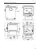
Baltic II Installation and Operation Manual 7.2 Clearances to Walls and Ceiling The clearances to combustible walls may be slightly different in Canada and the U.S.A. and may also differ depending on whether you use single or double wall flue pipe. Please be sure to choose the correct clearance for your location and type of flue pipe. See figure Clearances to combustible materials and floor protection to match each letter to a clearance.
Baltic II Installation and Operation Manual Clearances with ceiling (L) lowered to 72" (183 cm) APPLIANCE CLEARANCES (INSTALLATION WITH SINGLE WALL PIPE CONNECTOR) A B C K L CANADA USA 15" (381 mm) 12" (305 mm) 10" (254 mm) 48" (1220 mm) 72" (183 cm) 14" (356 mm) 12" (305 mm) 10" (254 mm) 48" (1220 mm) 72" (183 cm) APPLIANCE CLEARANCES (INSTALLATION WITH DOUBLE WALL PIPE CONNECTOR) A B C K L CANADA USA 8" (203 mm) 12" (305 mm) 10" (254 mm) 48" (1220 mm) 72" (183 cm) 8" (203 mm) 12" (305 mm) 10" (2
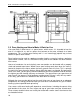
Baltic II Installation and Operation Manual If the above clearances are met, then the distances measured from the flue outlet will be: DISTANCES* FROM PIPE CONNECTOR TO THE COMBUSTIBLE MATERIALS D E F CANADA USA 12 1/2" (318 mm) 24" (610 mm) 17 1/2" (445 mm) 12 1/2" (318 mm) 24" (610 mm) 17 1/2" (445 mm) *The pipe distances listed in this table refer to the distances obtained when the stove is installed in accordance with the appliance clearances above mentioned.
Baltic II Installation and Operation Manual Clearances to combustible materials and floor protection 7.3 Floor protector Your stove has been conceived to prevent the floor from overheating. However, it must be placed on a noncombustible surface to protect the floor from hot embers that could fall from the stove while loading or cleaning.
Baltic II Installation and Operation Manual 7.4 Reducing Wall and Ceiling Clearances Safely It is often desirable to reduce the minimum installation clearances by placing the stove closer to walls so the installation takes up less floor space. You can safely reduce the minimum clearances by permanently installing a shield between the stove and combustible material. The rules for safe shields can be complicated, so read them carefully and follow them exactly.
Baltic II Installation and Operation Manual Clearances for shield construction 35
Baltic II Installation and Operation Manual 7.4.2 Table of Clearance Reduction Percentages Clearances may be reduced by these percentages Sides and rear % Type of shield Top % (ceiling) Can/US A (%) USA min. Can/US A (%) USA min.
Baltic II Installation and Operation Manual 8 The Venting System 8.1 General The venting system, made up of the chimney and the connecting pipe between the stove and the chimney, acts as the engine that drives your wood heating system. Even the best stove will not function safely and efficiently as intended if it is not connected to a suitable chimney. The heat in the flue gases that pass from the stove and chimney connector into the chimney is not waste heat.
Baltic II Installation and Operation Manual 8.2.2 Factory-built Metal Chimneys in mobile homes For use in a mobile home, this stove is to be connected to a 6” in diameter double wall factory built chimney conforming to CAN/ULC-S629, Standards for 650°C Factory-built chimney and to UL 103 HT Standard « Factory-Built Chimneys for Residential Type and Building Heating Appliances ». The total length of the flue system should be at least 12 feet including elbows, from the top of the stove.
Baltic II Installation and Operation Manual 8.3 Minimum Chimney Height The top of the chimney should be tall enough to be above the air turbulence caused when wind blows against the house and its roof. The chimney must extend at least 1 m (3 ft.) above the highest point of contact with the roof, and at least 60 cm (2 ft.) higher than any roof line or obstacle within a horizontal distance of 3 m (10 ft.). 8.
Baltic II Installation and Operation Manual Good System Design Inside chimneys are preferred because even when no fire is burning, there is normally upward flow in the system. Inferior System Design Outside chimneys are a problem because when no fire burns they will go into cold backdraft if the stove is installed low in the house. 8.4.2 Why the chimney should penetrate the highest heated space When it is cold outside, the warm air in the house is buoyant so it tends to rise.
Baltic II Installation and Operation Manual 8.5 Supply of Combustion Air In Canada, wood stoves are not required to have a supply of combustion air from outdoors (except in mobile homes) because research has shown that these supplies do not give protection against house depressurization and may fail to supply combustion air during windy weather.
Baltic II Installation and Operation Manual 8.6 Installing the Chimney Connector The chimney connector is the single or double wall pipe installed between the stove flue collar and the chimney breech. Single wall pipe components are available from most hardware and building supply stores. These components are not usually tested to a particular standard and certified as compliant. Therefore, a list of rules found in solid fuel installation codes apply to the installation of single wall pipe.
Baltic II Installation and Operation Manual Use 45° elbows where possible, instead of 90° elbows.
Baltic II Installation and Operation Manual The rules below are based on those found in the CSA B365 installation code. Please carefully follow these installation instruction rules, or those enforced where you live. • • • • • • • • • • • • • • • • Maximum overall length of straight pipe: 3 m (10 ft.) including elbows. Minimum clearance from combustible material: 450 mm (18 in.). The minimum clearance may be reduced by 50 percent to 225 mm (9 in.
Baltic II Installation and Operation Manual Appendix 1: Top Bricks Installation For transportation purpose, the top bricks have been laid on the bottom of the firebox. It is mandatory to install them on the brick supports before you operate the stove. Failure to install the bricks as describe bellow may result in stove damage and will void warrantee.
Baltic II Installation and Operation Manual Appendix 2: Installation of the Bypass Damper Handle Holder The bypass damper handle holder (A) can be installed using two screws (B) to the left or right side on the back heat shield of the stove. The screws and holder are provided with the manual kit.
Baltic II Installation and Operation Manual Appendix 3: Installing the Optional Fresh Air Intake kit (AC01336) When installed with a fresh air intake kit, the stove must be anchored to the floor This mobile home approved stove requires installation of a fresh air intake kit (A) and an insulated fresh air intake pipe (B), sold separately.
Baltic II Installation and Operation Manual Appendix 4: Installation and Use of the Optional Blower and Thermodisc An optional blower can be installed on the back of the stove to increase the flow of air past heat exchange surfaces and to help circulate warm air in the room. When used regularly, the blower can provide a small increase in efficiency, up to 2 percent.
Baltic II Installation and Operation Manual Appendix 5: Installation of Secondary Air Tubes and Baffle 1- Starting with the rear tube, lean and insert the right end of the secondary air tube into the rear right channel hole. Then lift and insert the left end of the tube into the rear left channel. 2- Align the notch in the left end of the tube with the key of the left air channel hole. Using a « Wise grip » hold the tube and lock it in place by turning the tube as shown in detail A.
Baltic II Installation and Operation Manual Note that secondary air tubes (B) can be replaced without removing the baffle board (A). HOW TO REMOVE AND REPLACE THE BAFFLES OF THE BYPASS DAMPER REGISTRE Follow the steps to remove the secondary air tubes (B) and the main baffle (A) as explained above. Remove the bypass baffles (C) as illustrated. Important Notes: The air tubes are identified for placement as follows: 50 Model Type of tube Baltic II Front ► 30 holes of 0.
Baltic II Installation and Operation Manual Appendix 6: Exploded Diagram and Parts List 51
Baltic II Installation and Operation Manual IMPORTANT: THIS IS DATED INFORMATION. When requesting service or replacement parts for your stove, please provide the model number and the serial number. We reserve the right to change parts due to technology upgrade or availability. Contact an authorized dealer to obtain any of these parts. Never use substitute materials. Use of non-approved parts can result in poor performance and safety hazards.
Baltic II Installation and Operation Manual # Item Description Qty 36 44085 RHEOSTAT KNOB 1 37 44087 RHEOSTAT NUT 1 38 44080 RHEOSTAT WITH NUT 1 39 AC02055 QUICK CONNECT THERMODISC KIT 1 39 AC05530 THERMODISC KIT 1 40 44046 THERMODISC F110-20F 1 41 PL36226 2 5/8" X 9" X 1" X 3 1/2" REFRACTORY BRICK 2 42 SE16059 ASH DUMP PLUG 1 43 PL36025 2 1/2" X 8" X 1 1/4" REFRACTORY BRICK 2 44 PL36022 4" X 5 1/4" X 1 1/4" REFRACTORY BRICK 1 45 29015 4'' x 9'' x 1 1/4'' REFRA
Baltic II Installation and Operation Manual DROLET LIMITED LIFETIME WARRANTY The warranty of the manufacturer extends only to the original retail purchaser and is not transferable. This warranty covers brand new products only, which have not been altered, modified nor repaired since shipment from factory. Proof of purchase (dated bill of sale), model name and serial number must be supplied when making any warranty claim to your DROLET dealer. This warranty applies to normal residential use only.