OWNER`S MANUAL Escape 1400-I Insert US ENVIRONMENTAL PROTECTION AGENCY PHASE II CERTIFIED WOOD INSERT Verified and tested following ULC S628 and UL 1482 Standards by: Manufactured by : STOVE BUILDER INTERNATIONAL INC.. 1700, Léon-Harmel, Québec (Québec) G1N 4R9 Tel : (418 ) 527-3060 Fax : (418 ) 527-4311 www.drolet.
INTRODUCTION SBI INC., one of the most important wood stove and fireplace manufacturers in Canada, congratulates you on your purchase and wishes to help you get maximum satisfaction from your wood insert. In the pages that follow, we will give you advice on wood heating and controlled combustion as well as technical specifications regarding installation, operation and maintenance of the model you have chosen.
TABLE OF CONTENTS INTRODUCTION...................................................................................................................................... 1 Section 1.0 Pre-Installation Requirements ............................................................................................. 4 1.1 Masonry & Zero Clearance Requirements .................................................................................. 4 1.2 Venting Requirements .......................................................
Escape 1400-I Dimensions 28 25/64" 26 29/32" 13 29/64" O 6.
Section 1.0 Pre-Installation Requirements 1.1 Masonry & Zero Clearance Requirements The masonry fireplace must meet the minimum code requirements, or NFPA 211 or the equivalent for a safe installation. Contact your local Building Inspector for requirements in your area. An inspection of the fireplace should include the following: 1.
1.2 Venting Requirements The flue is a critical component to a satisfactory installation. Your insert will attain its best performance if installed with a flue that generates its own draft. The minimum venting requirement will be the installation of a flue connector from the insert into the first tile of the chimney (see Figure 2.3).
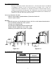
Section 2.0 Installation 2.1 Clearances To Combustibles (Measured From Insert Body) Sidewall (A) Top mantel (B) Side mantle (C) Shelf (D) Escape 1400-I 13” (330 mm) 22” (559 mm) 10” (254 mm) 29” (737 mm) Table 2.1 CLEARANCES Figure 2.1 Note: If side mantle protrudes more than 1.5” (38mm) in front of face of fireplace, then use sidewall clearance.
2.1.1 Hearth Requirements If the non-combustible hearth is flush with the floor, then the hearth must be 16”/406mm (18”/450mm in Canada) in front of the fan housing (see Figure 2.1.2). If the noncombustible hearth is a minimum of 4” (102mm) above the floor, then the hearth can be 6” (152mm) out from the fan housing with a 10” (254mm) floor protection (sparks) extended beyond the hearth (see Figure 2.1.1). The non-combustible hearth must be a minimum of 8” (203mm) on each side of the unit (Canada & USA).
2.3 Safety Information NOTE: This appliance is not recommended for use in a home if an occupant has any respiratory or any other related problems. 1. It is important to follow the installation and operation instructions. An improperly installed or operated insert could result in a safety hazard or fire, or damage to the unit, which would not be covered by the warranty. Contact local building or fire officials about restrictions and installation requirements in your area.
2.4 Installation Instructions 1. Inspect the fireplace according to the safety information and fireplace requirements and have it cleaned and/or upgraded as necessary. 2. If the installation of the unit renders the existing damper control inaccessible, it will be necessary to either secure the damper wide open or remove it entirely. An inaccessible damper, which may close, could cause smoke to enter the room. This creates a potential health hazard. 3.
2.5 Air control plate, faceplate and fan Assembly Instructions 1. Place the faceplate panels with the finished side down on a flat, soft, non-abrasive surface. 2. Assemble the faceplate trim, attaching the mitered corners with the corner brackets. (see Figure 2.4) 3. Line up the holes of the side and top panels and secure with the screws, washers and nuts. (see Figure 2.5a) 4. Slide the assembled trim over the edges of the faceplate. 5. Secure trim to faceplate using "U" shaped clips. (see Figure 2.
2.6 Installation of the adapter for fresh air kit In order to avoid some combustion problems, it is highly recommended to install an adapter for fresh air kit. To do so, you need to have the accessory #AC01298. Using pliers, remove the metal rectangle (A) located on the side of the insert. Choose the side that is best for your installation. Then, install the adapter for fresh air kit (B) using 4 screws (C).
Section 3.0 Operation 3.1 Safety Information 1. This insert is designed for safe operation WHEN BURNING CORDWOOD ONLY. Altering or modifying the unit or the installation without proper authorization will void the certification, warranty, and safety listing, and may result in a safety hazard. 2. For safety reasons, never leave the unit unattended with the door open or ajar.
air leakage into the unit, such as through deteriorated gaskets or cracked or broken glass. Do not operate the insert without a door gasket. Leakage can result in overheating, or in very airtight homes, could possibly cause smoke spillage into the room. Smoke may contain carbon monoxide, which is poisonous, and in sufficient quantities is a health hazard. 11. We recommend that you have a fresh air or make up air supply for the insert. In Canada this is a building code requirement.
An example of the energy values of some common wood fuels is given in Table 3.1 For recommended wood sizes, refer to the specifications. Common Heating Values of Cordwood Hardwoods Birch White Oak Alder Million Btu/Cord 23.6 28.3 17.6 Table 3.1 Softwoods Douglas Fir Hemlock Jack Pine Million Btu/Cord 20.6 17.1 18.4 3.2.1 Simple Wood Moisture Test Add one large piece of wood to the top of an established fire.
6. Ideally the large kindling should be burned until a thick bed of red embers is obtained. At that point, add cordwood fuel and continue to operate the draft control wide open until the fire is well established. Once the firebox is hot, the draft control can be partially closed by moving the knob to the left to adjust the intensity of the fire. Use Table 3.
3.5 Maintaining The Fire Your Drolet insert will work best if a thick bed of hot embers is maintained in the bottom of the firebox, and a minimum of two large pieces of seasoned fuel are added. Combustion efficiency is largely related to establishing a hot ember bed, and hot firebox temperatures. The quicker the insert and fuel get up to operating temperature, the better.
Section 4.0 Maintenance 4.1 Care And Cleaning Clean the insert frequently so that soot, ash and creosote do not accumulate. Do not attempt to clean the insert, glass or door when the unit is hot. Special care must be taken with plated surfaces in order to maintain the finish at its original brilliance. Do not use an abrasive glass cleaner which will scratch the glass or plated finish. Use only a soft clean damp cloth on the door, since some cleaners may remove the plating or paint. 4.1.
4.2 Ash Removal CAUTION: Ashes can start fires, even after several days of inactivity. Never dispose of ashes in a combustible container. Remove ashes only when the insert and ashes are cold. Ashes should be removed from the insert frequently. When ashes are removed, they should be placed in a metal container with a tightly fitting lid. The closed container of ashes should be placed on a noncombustible floor or on the ground, well away from all combustible materials, pending final disposal.
4.4 Baffle Installation for Escape 1400-I WOOL WEIGHT INSULATION BLANKET VERMICULITE BAFFLE BOARD MIDDLE AND REAR TUBES FRONT TUBE FRONT BAFFLE SUPPORT Figure 4.1 – Baffle installation & removal for Escape 1400-I The baffle assembly must be properly in place for correct burning operation. Have any damaged firebricks replaced. Check the firebricks annually for damage and replace if they are broken or damaged. See Figure 3.3 for the firebrick layout.
4.5 Secondary Air Tube Replacement (see Figure 4.3) 1. Remove cotter pin at RH end of tube. 2. Slide tube to left and lower tube end below RH plenum. 3. Slide tube to right to remove. 4. Reassemble in reverse order using a new cotter pin. The cotter pin is a hammerlock style and locks into place by hitting the head sharply with a hammer. 5. Note that any tube can be replaced without disturbing the baffle.
4.6 Fan Maintenance & Care Clean the fan air inlet louvres and squirrel cage impeller regularly. The fan should be kept clean and dust free. Life of the fan will be shortened if operated in a dust filled environment, or if the fan is overheated by restricting air supply. Stalling the rotor, or over firing the insert with the fan turned off will also damage the fan. The fan must not be overheated. Do not disassemble the fan. "ALTERING OR TAMPERING WITH THE FAN WILL VOID THE WARRANTY". 4.
Section 5.0 Specifications 5.1 Escape 1400-I Insert Model Fuel Type Cordwood Test Standards ULC S628 (CSA B366.2) & UL 1482 residential. Recommended surface : 700 to 1600 sq. ft. Heating capacity* – BTU/hr., EPA test wood: 39,000 BTU/h. Heating capacity* – BTU/hr., seasoned cordwood : 60,000 BTU/h.
DROLET LIMITED LIFETIME WARRANTY The warranty of the manufacturer extends only to the original consumer purchaser and is not transferable. This warranty covers brand new products only, which have not been altered, modified nor repaired since shipment from factory. Proof of purchase (dated bill of sale), model name and serial number must be supplied when making any warranty claim to your DROLET dealer. This warranty applies to normal residential use only.