Installation and Operation Manual Pyropak (DB03180 model) US ENVIRONMENTAL PROTECTION AGENCY PHASE II CERTIFIED WOOD STOVE Safety tested according to ULC S627, UL 737 and UL 1482 Standards by an accredited laboratory www.drolet.ca Stove Builder International Inc. 250, rue de Copenhague, St-Augustin-de-Desmaures (Quebec) Canada G3A 2H3 After-sale service: 418-908-8002 E-mail: tech@sbi-international.com This manual is available for free download on the manufacturer’s web site. It is a copyrighted document.
Pyropak Installation and Operation Manual THANK YOU FOR CHOOSING THIS DROLET WOOD STOVE As one of North America’s largest and most respected wood stove and fireplace manufacturers, Stove Builder International takes pride in the quality and performance of all its products. We want to help you get maximum satisfaction as you use this product.
Pyropak Installation and Operation Manual Table of content PART A - OPERATION AND MAINTENANCE ...............................6 1 Safety Information ....................................................................6 1.1 2 Summary of Operation and Maintenance Cautions and Warnings ......................... 6 General Information on Pyropak (DB03180) ..........................7 2.1 Appliance performance(1) ....................................................................................... 7 2.
Pyropak Installation and Operation Manual 5 Maintaining Your Wood Heating System..............................23 5.1 Stove Maintenance............................................................................................... 23 5.1.1 Cleaning Door Glass ......................................................................................... 23 5.1.2 Door adjustment ................................................................................................ 24 5.1.3 Replacing the Door Gasket ...
Pyropak Installation and Operation Manual Appendix 1: Installing the Optional Fresh Air Intake Kit (AC01331) ................................................................42 Appendix 2: Installation and Use of the Optional Blower and Thermodisc .............................................................43 Appendix 3: Installing the Optional Fire Screen (AC01318) .....45 Appendix 4: Exploded Diagram and Parts List ..........................46 DROLET LIMITED LIFETIME WARRANTY ............................
Pyropak Installation and Operation Manual PART A - OPERATION AND MAINTENANCE Please see Part B for installation instructions. 1 Safety Information 1.1 Summary of Operation and Maintenance Cautions and Warnings • HOT WHILE IN OPERATION, KEEP CHILDREN, CLOTHING AND FURNITURE AWAY. CONTACT MAY CAUSE SKIN BURNS. GLOVES MAY BE NEEDED FOR STOVE OPERATION. • USING A STOVE WITH CRACKED OR BROKEN COMPONENTS, SUCH AS GLASS OR FIREBRICKS OR BAFFLES MAY PRODUCE AN UNSAFE CONDITION AND MAY DAMAGE THE STOVE.
Pyropak Installation and Operation Manual 2 General Information on Pyropak (DB03180) 2.1 Appliance performance(1) Fuel type Dry cordwood Recommended heating area[*] 250 to 1,000 ft2 (23 to 93 m2) Firebox volume 1.3 ft3 (0.037 m3) Maximum burn time[*] 5h Maximum heat output(2) (dry cordwood) 40,000 BTU/h (11.7 kW) Overall heat output rate (min. to max.)(2)(3) 10,800 BTU/h to 22,600 BTU/h (3.2 kW to 6.
Pyropak Installation and Operation Manual 2.
Pyropak Installation and Operation Manual 9
Pyropak Installation and Operation Manual 2.3 Zone Heating and How to Make it Work for You Your new Pyropak wood stove is a space heater, which means it is intended to heat the area it is installed in, as well as spaces that connect to that area, although to a lower temperature. This is called zone heating and it is an increasingly popular way to heat homes or spaces within homes.
Pyropak Installation and Operation Manual 2.4 The Benefits of Low Emissions and High Efficiency The low smoke emissions produced by the special features inside the Pyropak firebox mean that your household will release up to 90 percent less smoke into the outside environment than if you used an older conventional stove. But there is more to the emission control technologies than protecting the environment. The smoke released from wood when it is heated contains about half of the energy content of the fuel.
Pyropak Installation and Operation Manual 3 Fuel 3.1 Materials That Should Not be Burned • GARBAGE OF ANY KIND, • COAL OR CHARCOAL, • TREATED, PAINTED OR COATED WOOD, • PLYWOOD OR PARTICLE BOARD, • FINE PAPER, COLORED PAPER OR CARDBOARD, • SALT WATER DRIFTWOOD, • MANUFACTURED LOGS CONTAINING WAX OR CHEMICAL ADDITIVES, • RAILROAD TIES, • LIQUIDS SUCH AS KEROSCENE OR DIESEL FUEL TO START A FIRE. 3.2 How to Prepare or Buy Good Firewood 3.2.
Pyropak Installation and Operation Manual 3.2.3 Log Length Logs should be cut about 1” (25 mm) shorter than the firebox so they fit in easily. Pieces that are even slightly too long make loading the stove very difficult. The most common standard length of firewood is 16” (400 mm). The pieces should be a consistent length, with a maximum of 1” (25 mm) variation from piece to piece. 3.2.4 Piece Size Firewood dries more quickly when it is split. Large unsplit rounds can take years to dry enough to burn.
Pyropak Installation and Operation Manual 3.2.5 How to Dry Firewood Firewood that is not dry enough to burn is the cause of most complaints about wood stoves. The complaints usually involve a lack of heat and dirty door glass.
Pyropak Installation and Operation Manual 3.2.
Pyropak Installation and Operation Manual 4 Operating Your Stove 4.1 The use of a fire screen. This stove has been tested for use with an open door in conjunction with a fire screen (AC01318, sold separately). Make sure the fire screen is properly secured on the stove to avoid any risk of fire. When the fire screen is used, it is important not to leave the stove unattended to respond promptly in the event of smoke spillage into the room.
Pyropak Installation and Operation Manual 4.3.1 Conventional Fire Starting The conventional way to build a wood fire is to bunch up 5 to 10 sheets of plain newspaper and place them in the firebox. Next, place 10 or so pieces of fine kindling on the newspaper. This kindling should be very thin; less than 1” (25 mm). Next, place some larger kindling pieces on the fine kindling. Open the air control fully and light the newspaper.
Pyropak Installation and Operation Manual 4.3.3 Two Parallel Logs Place two spit logs in the firebox. Place a few sheets of twisted newspaper between the logs. Now place some fine kindling across the two logs and some larger kindling across those, log cabin style. Light the newspaper. 4.3.4 Using Fire Starters Many people like to use commercial fire starters instead of newspaper. Some of these starters are made of sawdust and wax and others are specialized flammable solid chemicals.
Pyropak Installation and Operation Manual 4.4.2 Ash Removal Ash should be removed from the firebox every two or three days of full time heating. Do not let the ash build up in the firebox because it will interfere with proper fire management. The best time to remove ash is after an overnight fire when the stove is relatively cool, but there is still some chimney draft to draw the ash dust into the stove and prevent it from coming into the room.
Pyropak Installation and Operation Manual 4.4.4 Firing Each New Load Hot Place the new load of wood on and behind the charcoal. Close the door and open the air control fully. Leave the air control fully open until the firebox is full of flames, the wood has charred to black and its edges are glowing red.
Pyropak Installation and Operation Manual 4.4.6 Building Different Fires for Different Needs Using the air control is not the only way to match the stove’s heat output to the heat demand. Your house will need far less heat in October than in January to be kept at a comfortable temperature. If you fill the firebox full in fall weather, you will either overheat the space or turn the stove down so much that the fire will be smoky and inefficient.
Pyropak Installation and Operation Manual The table below provides a very general indication of the maximum burn cycle times you are likely to experience, based on firebox volume. <1.5 cubic feet MAXIMUM BURN TIME 3 to 5 hours 1.5 c.f. to 2.0 c.f 5 to 6 hours 2.0 c.f. to 2.5 c.f. 6 to 8 hours 2.5 c.f. to 3.0 c.f. 8 to 9 hours >3.0 c.f. 9 to 10 hours FIREBOX VOLUME Long burn times are not necessarily an indication of efficient stove operation.
Pyropak Installation and Operation Manual 5 Maintaining Your Wood Heating System 5.1 Stove Maintenance Your new stove will give many years of reliable service if you use and maintain it correctly. Some of the internal components of the firebox, such as firebricks, baffles and air tubes, will wear over time under intense heat. You should always replace defective parts with original parts (see Appendix 4: Exploded Diagram and Parts List).
Pyropak Installation and Operation Manual 5.1.2 Door adjustment In order for your stove to burn at its best efficiency, the door must provide a perfect seal with the firebox. Therefore, the gasket should be inspected periodically making sure to obtain an air tight fit. Airtightness can be improved with a simple latch mechanism adjustment. To adjust: 1. Remove the lock pin (spring pin) by pulling and turning it using pliers. 2. Turn the handle counter clock wise one turn to increase pressure. 3.
Pyropak Installation and Operation Manual Place the door face-down on something soft like a cushion of rags or piece of carpet. Remove the old gasket from the door by pulling and prying it out with an old screw driver. Then use the screwdriver to scrape the old gasket adhesive from the door. Now run a 1/4” (6 mm) bead of high temperature silicone in the door gasket groove. Starting from the middle of the hinge side, press the gasket into the groove. Do not stretch the gasket as you place it.
Pyropak Installation and Operation Manual 5.1.5 Cleaning and Painting the Stove Do not attempt to clean or paint the stove when the unit is hot. Painted surfaces can be wiped down with a damp cloth. Plated surfaces may be scratched by abrasive cleaners. To maintain the finish at its original brilliance, use only a damp soft cloth to clean plated surfaces. If the paint becomes scratched or damaged, you can give your wood stove a brand new look by repainting it with heat-resistant paint.
Pyropak Installation and Operation Manual 5.2.3 Cleaning the Chimney Chimney cleaning can be a difficult and dangerous job. If you don’t have experience cleaning chimneys, you might want to hire a professional chimney sweep to clean and inspect the system for the first time. After having seen the cleaning process, you can decide if it is a job you would like to take on. The most common equipment used are fibreglass rods with threaded fittings and stiff plastic brushes.
Pyropak Installation and Operation Manual PART B - INSTALLATION 6 Safety Information 6.1 Summary of Installation Cautions and Warnings • THE INFORMATION GIVEN ON THE CERTIFICATION LABEL AFFIXED TO THE APPLIANCE ALWAYS OVERRIDES THE INFORMATION PUBLISHED, IN ANY OTHER MEDIA (OWNER’S MANUAL, CATALOGUES, FLYERS, MAGAZINES AND/OR WEB SITES). • MIXING OF APPLIANCE COMPONENTS FROM DIFFERENT SOURCES OR MODIFYING COMPONENTS MAY RESULT IN HAZARDOUS CONDTIONS.
Pyropak Installation and Operation Manual 7 Clearances to Combustible Material The clearances shown in this section have been determined by test according to procedures set out in safety standards ULC S627 (Canada), UL1482 (U.S.A.) and UL737 (U.S.A.). When the stove is installed so that its surfaces are at or beyond the minimum clearances specified, combustible surfaces will not overheat under normal and even abnormal operating conditions.
Pyropak Installation and Operation Manual If the above clearances are met, then the distances measured from the flue outlet will be: DISTANCES* FROM PIPE CONNECTOR TO THE COMBUSTIBLE MATERIALS D E F CANADA 18" (457 mm) 26½" (673 mm) 18" (457 mm) USA 17¾" (451 mm) 26½" (673 mm) 18" (457 mm) DISTANCES* FROM PIPE CONNECTOR TO THE COMBUSTIBLE MATERIALS D E F CANADA 12¾" (324 mm) 26½" (673 mm) 18" (457 mm) USA 12¾" (324 mm) 26½" (673 mm) 18" (457 mm) *The pipe distances listed in this table refer to the d
Pyropak Installation and Operation Manual If the above clearances are met, then the distances measured from the flue outlet will be: DISTANCES* FROM PIPE CONNECTOR TO THE COMBUSTIBLE MATERIALS D E F CANADA 18" (457 mm) 26½" (673 mm) 20" (508 mm) USA 17¾" (451 mm) 26½" (673 mm) 20" (508 mm) DISTANCES* FROM PIPE CONNECTOR TO THE COMBUSTIBLE MATERIALS D E F CANADA 14¾" (375 mm) 26½" (673 mm) 18" (457 mm) USA 14¾" (375 mm) 26½" (673 mm) 18" (457 mm) *The pipe distances listed in this table refer to the d
Pyropak Installation and Operation Manual Clearances to combustible materials and floor protection 7.3 Floor protector If the stove is to be installed on top of a combustible floor, it must be guarded by a non combustible material as shown on figure 1.3 (see the dotted line area).
Pyropak Installation and Operation Manual 7.4 Reducing Wall and Ceiling Clearances Safely It is often desirable to reduce the minimum installation clearances by placing the stove closer to walls so the installation takes up less floor space. You can safely reduce the minimum clearances by permanently installing a shield between the stove and combustible material. The rules for safe shields can be complicated, so read them carefully and follow them exactly.
Pyropak Installation and Operation Manual Clearances for shield construction 34
Pyropak Installation and Operation Manual 7.4.2 Table of Clearance Reduction Percentages Clearances may be reduced by these percentages Sides and rear % Type of shield Top % (ceiling) Can/US A (%) USA min. Can/US A (%) USA min.
Pyropak Installation and Operation Manual 8 The Venting System 8.1 General The venting system, made up of the chimney and the connecting pipe between the stove and the chimney, acts as the engine that drives your wood heating system. Even the best stove will not function safely and efficiently as intended if it is not connected to a suitable chimney. The heat in the flue gases that pass from the stove and chimney connector into the chimney is not waste heat.
Pyropak Installation and Operation Manual 8.2.2 Masonry Chimneys The stove may also be connected to a masonry chimney, provided the chimney complies with the construction rules found in the building code enforced locally. The chimney must have either a clay liner or a suitably listed stainless steel liner. If the masonry chimney has a square or rectangular liner that is larger in cross sectional area than a round 6” flue, it should be relined with a suitably listed 6” stainless steel liner.
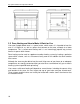
Pyropak Installation and Operation Manual 8.4 The Relationship Between the Chimney and the House Because the venting system is the engine that drives the wood heating system, it must have the right characteristics. The signs of bad system design are cold backdrafting when there is no fire in the stove, slow kindling of new fires, and smoke roll-out when the door is opened for loading. There are two guidelines to follow.
Pyropak Installation and Operation Manual There are two reasons why the chimney in the house at right will cold backdraft when it is cold outside and there is no fire burning in the stove. First, the chimney runs up the outside of the house, so the air in it is colder and denser than the warm air in the house. And second, the chimney is shorter than the heated space of the house, meaning the negative pressure low in the house will pull outside air down the chimney, through the stove and into the room.
Pyropak Installation and Operation Manual 8.6 Installing the Chimney Connector The chimney connector is the single or double wall pipe installed between the stove flue collar and the chimney breech. Single wall pipe components are available from most hardware and building supply stores. These components are not usually tested to a particular standard and certified as compliant. Therefore, a list of rules found in solid fuel installation codes apply to the installation of single wall pipe.
Pyropak Installation and Operation Manual The rules below are based on those found in the CSA B365 installation code. Please carefully follow these installation instruction rules, or those enforced where you live. • • • • • • • • • • • • • • • • Maximum overall length of straight pipe: 3 m (10 ft.) including elbows. Minimum clearance from combustible material: 450 mm (18 in.). The minimum clearance may be reduced by 50 percent to 225 mm (9 in.
Pyropak Installation and Operation Manual Appendix 1: Installing the Optional Fresh Air Intake Kit (AC01331) The installation instructions are provided with the Fresh Air Intake Kit (AC01331), sold separately.
Pyropak Installation and Operation Manual Appendix 2: Installation and Use of the Optional Blower and Thermodisc An optional blower can be installed on the back of the stove to increase the flow of air past heat exchange surfaces and to help circulate warm air in the room. When used regularly, the blower can provide a small increase in efficiency, up to 2 percent.
Pyropak Installation and Operation Manual The blower has a rheostat, see the illustration on the right to identify the different adjustment positions; either from high (HI) to low (LO) or closed (OFF). When using the optional blower, allow the stove to reach operating temperature (approximately one hour), before turning it on. The increased airflow from the blower cools the firebox and could affect the start-up combustion efficiency if the blower is turned on too early.
Pyropak Installation and Operation Manual Appendix 3: Installing the Optional Fire Screen (AC01318) Open the door. Hold the fire screen by the two handles and bring it close to the door opening. Lean the upper part of the fire screen against the top door opening making sure to insert the top fire screen brackets behind the primary air deflector as in (Detail A). Lift the fire screen upwards and push the bottom part towards the stove then let the fire screen rest on the bottom of the door opening.
Pyropak Installation and Operation Manual Appendix 4: Exploded Diagram and Parts List 46
Pyropak Installation and Operation Manual # Item # 1 2 3 4 5 6 7 8 9 10 11 12 13 14 15 AC01318 30569 AC07867 SE24112 AC09155 AC09185 AC06500 30055 30169 30101 SE63002 AC06400 PL54583 SE53585 PL63249 16 30060 17 18 19 20 21 22 23 24 25 26 27 28 29 30 31 32 33 34 34 35 36 37 38 39 99999 AC01331 99999 AC07863 30125 PL63324 30094 30428 SE63323 SE45397 AC05959 AC02050 60013 44073 44080 44087 44085 AC02055 AC05530 44046 29015 29010 21386 PL63339 Description RIGID FIRESCREEN ROUND WOODEN HANDLE BLACK 1/2
Pyropak Installation and Operation Manual DROLET LIMITED LIFETIME WARRANTY The warranty of the manufacturer extends only to the original retail purchaser and is not transferable. This warranty covers brand new products only, which have not been altered, modified nor repaired since shipment from factory. Proof of purchase (dated bill of sale), model name and serial number must be supplied when making any warranty claim to your DROLET dealer. This warranty applies to normal residential use only.