OWNER`S MANUAL DROLET EPA WOODSTOVES HT-1600 & HT-2000 US ENVIRONMENTAL PROTECTION AGENCY PHASE II CERTIFIED WOODSTOVES Vérified and tested following ULC S627 et UL 1482 Standards by: READ AND KEEP THIS MANUAL FOR REFERENCE Manufactured by : STOVE BUILDER INTERNATIONAL 1700, Léon-Harmel, Québec (Québec) G1N 4R9 Tel : ( 418 ) 527-3060 Fax : ( 418 ) 527-4311 www.drolet.ca Revised : May 15th, 2009 INC.
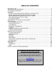
TABLE OF CONTENTS INTRODUCTION .................................................................................................................... 2 TECHNICAL SPECIFICATIONS ............................................................................................ 3 TIPS ON WOOD HEATING ................................................................................................... 4 ASSEMBLY ..............................................................................................................
INTRODUCTION SBI INC., one of the most important wood stove and fireplace manufacturers in Canada, congratulates you on your purchase and wishes to help you get maximum satisfaction from your wood stove. In the pages that follow, we will give you advice on wood heating and controlled combustion as well as technical specifications regarding installation, operation and maintenance of the model you have chosen.
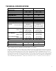
TECHNICAL SPECIFICATIONS HT-1600 HT-2000 Wood Combustion Type: Wood 2 Recommended Surface Heating Capacity* : E.P.
TIPS ON WOOD HEATING Wood is a renewable energy. It is also a very clean heat source when used with appliances that are certified by the U.S. Environmental Protection Agency (EPA), a standard accepted in Canada as well. EPA-certified wood stoves are different than conventional wood stoves. Burning with an EPA-certified wood stove may therefore require that you modify some of your heating habits.
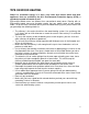
ASSEMBLY PEDESTAL AND DECORATIVE SIDEWALL INSTALLATION Pedestal Installation : 1. Remove all bricks and insulations in the appliance. 2. Slowly, lay down the stove on his back. 3. Install legs or the pedestal with the supplied nuts and bolts. Stand up the stove and place it with the required clearances. Note that there is eight holes in the bottom of the stove but only four will align with the pedestal. 4.
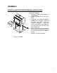
BRICKS AND INSULATION INSTALLATION (HT-1600) 1. 2. 3. 4. 5. 6. 7. Remove from the stove all bricks and insulation. Install all side bricks (11 x 4 1/2" x 9" & 1 x 4 ½” x 8 3/16") as shown in drawing below. Install the back bricks (6 x 4 1/2" x 9") Install the bottom bricks (4 x 4 1/2" x 9") + (2 x 6 " x 8") and the ash cap. Install the "T" shape support. Install the baffle bricks (4 x 4 1/2" x 9") + (2 x 3" x 9") on T shape support. Finally, gently slide the insulation panels over the baffle bricks. Nbr.
BRICK AND INSULATION INSTALLATION (HT-2000) The stove is normally supplied with secondary air tubes in position. To install the baffle bricks and white ceramic insulation, it’s necessary to remove the two front secondary air tubes. First place only one baffle brick and one white ceramic insulation. Use the same method to put the other baffle brick and insulation. Put back in place the secondary air tubes. Install the yellow insulation and the 6" x 8" or 6" x 6" bricks. Install the side and bottom bricks.
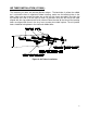
AIR TUBES INSTALLATION (HT-2000): The secondary air tubes are painted different colours . The back tube is yellow, the middle on is red and the front is unpainted. Before installing, make sure the locating holes in the tubes (holes near one end of the tube) are on the left side. Insert one tube in the right side air channel and slide it to the right as much as possible. Bring the left end of the tube aligned with the ring welded to the left air channel.
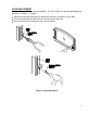
DOOR ADJUSTMENT In order for your stove to operate properly, the door should be adjusted periodically to provide an air tight fit.
THE BENEFITS OF INSTALLING A BLOWER A blower can be installed at the back of your DROLET stove. This option is necessary if you wish to redistribute into a room the heat trapped at the back of your stove. By forcing hot air toward the front, the blower enables you to extend the radiation power of your stove. You can purchase this option through your DROLET dealer. Make sure to specify this part number: #AC02050.
INSTALLATION SAFETY NOTICE IF THIS STOVE IS NOT PROPERLY INSTALLED, A HOUSE FIRE MAY RESULT. TO REDUCE THE RISK OF FIRE, FOLLOW THE INSTALLATION INSTRUCTIONS. FAILURE TO FOLLOW INSTRUCTIONS MAY RESULT IN PROPERTY DAMAGE, BODILY INJURY, OR EVEN DEATH. CONSULT YOUR MUNICIPAL BUILDING DEPARTMENT OR FIRE OFFICIALS ABOUT RESTRICTIONS AND INSTALLATIONS REQUIREMENTS IN YOUR AREA. USE SMOKE DETECTORS IN THE ROOM WHERE YOUR STOVE IS INSTALLED. KEEP FURNITURE AND DRAPES WELL AWAY FROM THE STOVE.
FLOOR PROTECTOR Your wood stove should be placed on a non-combustible surface. The floor protector should be under the stove, eighteen inches beyond the front and eight inches beyond each side of the fuel loading and ash removal opening. If there is a horizontal section of chimney connector, the floor protector should go under it and two inches beyond each side.
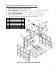
CLEARANCES It is of utmost importance that the clearances to combustible material be scrupulously respected upon installation of the stove you have selected. Refer to the tables below : Figure 6: Clearances to combustibles CANADA Model HT-1600 HT-2000 Single pipe / Double pipe A 15/12 19/10 USA Model HT-1600 HT-2000 B 16/16 19/14 C 12/10 11/8 D E F 20.8/17.8 28.7/28.7 25.2/23.2 25.4/16.4 33.1/28.1 25.5/22.5 Single pipe / Double pipe A 15/12 19/10 B 16/16 19/14 C 12/10 11/8 D E F 20.8/17.8 28.7/28.
REDUCED CLEARANCES You may decrease the clearances by installing heat radiation shields between the walls or the ceiling and the stove. These heat radiation shields must be installed permanently, and can include sheet metal, a rigid non-combustible sheet or a masonry wall.
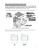
Graphic 1 A- Clearance to combustible material with no protection. B- 500 mm (20 po.) minimum; C- 25 mm (1 po.) minimum; D- Between 25 mm (1 po.) and 75 mm (3 po.) ; E- 75 mm (3 po.) minimum; F- 450 mm (18 po.) minimum. 1- Wall shielding ; 2- Non-combustible spacers ; 3- Ceiling shielding ; 4- Combustible wall ; 5- Ceiling; 6- Heater (side view) ; 7- Heater (top view).
A- 25 mm (1 po.) minimum; 1- Combustible wall ; 2- Non-combustible spacer; 3- 0.61 mm (0.024") sheet metal. Graphic 3 A- 25 mm (1 po.) minimum; 1- Combustible wall; 2- Non-combustible spacer; 3- Fire-proof support; 4- Ceramic tile or equivalent non-combustible material. _____________________________________________________________________________ Graphic 4 A- 25 mm (1 po.) minimum; 1- Combustible wall; 2- Non-combustible spacer; 3- 0.61 mm (0.
Graphic 5 A- 25 mm (1 po.) minimum; 1- Combustible wall; 2- Non-combustible spacer; 3- Brick. Graphic 6 A- 25 mm (1 po.) minimum; 1- Combustible wall; 2- Non-combustible spacer; 3- 0.61 mm (0.024") sheet metal; 4- Brick.
CHIMNEY Your wood stove may be hooked up with a factory built or masonry chimney. If you are using a factory built chimney, it must comply with UL 103 or ULC S629 standards; therefore it must be a Type HT (2100°F). It is extremely important that it be installed according to the manufacturer's specifications. If you are using a masonry chimney, it is important that it be built in compliance with the specifications of the National Building Code.
CHIMNEY CONNECTOR (STOVE PIPE) Your chimney connector and chimney must have the same diameter as the stove outlet. If this is not the case, we recommend you contact your dealer in order to insure there will be no problem with the draught. The stove pipe must be made of aluminized or cold roll steel with a minimum thickness of 0.021" or 0.53 mm. It is strictly forbidden to use galvanized steel. Your smoke pipe should be assembled in such a way that the male section of the pipe faces down.
TYPICAL INSTALLATIONS FACTORY BUILT CHIMNEY: RAIN CAP ROOF FLASHING 18" CLEARANCE RADIATION SHIELD WALL RADIATION SHIELD WALL SUPPORT CEILING SUPPORT Wall installation Vertical installation 20
MASONRY CHIMNEY: Clay liner Thimble Clean out door 21
FACTORY BUILT THIMBLE: 22
BRICK THIMBLE: 23
Avoid 90 degree eblows We recommend that you use two 45 degree elbows instead 24
WOODSTOVE UTILIZATION Your heating unit was designed to burn wood only; no other materials should be burnt. Wastes and other flammable materials should not be burnt in your wood stove. Any type of wood may be used in your stove, but specific varieties have better energy yields than others. Please consult the following table in order to make the best possible choice.
Smaller pieces of wood will dry faster. All logs exceeding 6" in diameter should be split. The wood should not be stored directly on the ground. Air should circulate through the cord. A 24" to 48" air space should be left between each row of logs, which should be placed in the sunniest location possible. The upper layer of wood should be protected from the element but not the sides.
HEATING Controlled combustion is the most efficient technique for wood heating because it enables you to select the type of combustion you want for each given situation. The wood will burn slowly if the wood stove air intake control is adjusted to reduce the oxygen supply in the combustion chamber to a minimum. On the other hand, wood will burn quickly if the air control is adjusted to admit a larger quantity of oxygen in the combustion chamber. The air intake control on your stove is very simple.
Note regarding the HT2000 : In order to achieve an optimum efficiency from your unit, we suggest that you operate it with the air control completely closed. Make sure that you have a good fire going and an adequate ember bed before you completely close the air control. Use a chimney thermometer if necessary. Closing the air control too soon will lower combustion efficiency and may cause the fire to die out.
TO PREVENT CREOSOTE BUILD UP Always burn dry wood. This allows clean burns and higher chimney temperatures, therefore less creosote deposit. Leave the air control fully open for about 10 min. every time you reload the stove to bring it back to proper operating temperatures. The secondary combustion can only take place if the firebox is hot enough. Always check for creosote deposit once every two months and have your chimney cleaned at least once a year.
MAINTENANCE Your Drolet stove is a high efficiency stove and therefore require little maintenance. It is important to perform a visual inspection of the stove every time it is emptied, in order to insure that no parts have been damaged, in which case repairs must be performed immediately. GLASS Inspect the glass regularly in order to detect any cracks. If you spot one, turn the stove off immediately. Do not abuse the glass door by striking or slamming shut. Do not use the stove if the glass is broken.
DROLET LIMITED LIFETIME WARRANTY The warranty of the manufacturer extends only to the original consumer purchaser and is not transferable. This warranty covers brand new products only, which have not been altered, modified nor repaired since shipment from factory. Proof of purchase (dated bill of sale), model name and serial number must be supplied when making any warranty claim to your DROLET dealer. This warranty applies to normal residential use only.