Installation and Operation Manual HT-2000 US ENVIRONMENTAL PROTECTION AGENCY PHASE II CERTIFIED WOOD STOVE Safety tested according to ULC S627, and UL 1482 Standards by Intertek Testing Services www.drolet.ca Stove Builder International Inc. 250, rue de Copenhague, St-Augustin-de-Desmaures (Quebec) Canada G3A 2H3 Tel: (418) 878-3040 Fax: (418) 878-3001 This manual is available for free download on the manufacturer’s web site. It is a copyrighted document. Re-sale is strictly prohibited.
HT-2000 Installation and Operation Manual THANK YOU FOR CHOOSING THIS DROLET WOOD STOVE As one of North America’s largest and most respected wood stove and fireplace manufacturers, Stove Builder International takes pride in the quality and performance of all its products. We want to help you get maximum satisfaction as you use this product.
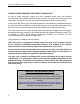
HT-2000 Installation and Operation Manual Table of content PART A - OPERATION AND MAINTENANCE ...............................6 2 Safety Information .....................................................................6 2.2 2.1 2.2 2.3 2.4 2.4.1 Summary of Operation and Maintenance Cautions and Warnings ......................... 6 HT-2000 Specifications .......................................................................................... 7 Zone Heating and How to Make it Work for You .................
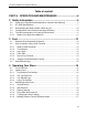
HT-2000 Installation and Operation Manual 5 Maintaining Your Wood Heating System ...............................23 5.1 Stove Maintenance............................................................................................... 23 5.1.1 Plated Finish Maintenance ................................................................................ 23 5.1.2 Cleaning Door Glass ......................................................................................... 23 5.1.3 Door adjustment ...................
HT-2000 Installation and Operation Manual 8.6 Installing the Chimney Connector......................................................................... 41 8.6.1 Installation of Single Wall Chimney Connector ................................................. 42 Appendix 1: Installing the Pedestal ............................................44 Appendix 2: Installing Trims ........................................................
HT-2000 Installation and Operation Manual PART A - OPERATION AND MAINTENANCE Please see Part B for installation instructions. 2 Safety Information 2.2 Summary of Operation and Maintenance Cautions and Warnings • HOT WHILE IN OPERATION, KEEP CHILDREN, CLOTHING AND FURNITURE AWAY. CONTACT MAY CAUSE SKIN BURNS. GLOVES MAY BE NEEDED FOR STOVE OPERATION. • USING A STOVE WITH CRACKED OR BROKEN COMPONENTS, SUCH AS GLASS OR FIREBRICKS OR BAFFLES MAY PRODUCE AN UNSAFE CONDITION AND MAY DAMAGE THE STOVE.
HT-2000 Installation and Operation Manual 2 General Information 2.1 HT-2000 Specifications Fuel Type Cordwood Test Standards (safety) ULC S627 and UL 1482 Test Standard (emissions) EPA Method 28 (40 CFR Part 60) Heating capacity range* 1,000 to 2,400 sq. ft. (93 to 223 m2) Maximum heat output** (EPA test fuel) Maximum heat output** (natural hardwood fuel) 60, 175 BTU/h (17.64 kW/h) 95,000 BTU/h (27.84 kW/h) Optimum efficiency 78 % Particulate Emissions 3.
HT-2000 Installation and Operation Manual 8
HT-2000 Installation and Operation Manual 9
HT-2000 Installation and Operation Manual 2.2 Zone Heating and How to Make it Work for You Your new HT-2000 wood stove is a space heater, which means it is intended to heat the area it is installed in, as well as spaces that connect to that area, although to a lower temperature. This is called zone heating and it is an increasingly popular way to heat homes or spaces within homes.
HT-2000 Installation and Operation Manual 2.4 The SBI Commitment to You and the Environment The SBI team is committed to protecting the environment, so we do everything we can to use only materials in our products that will have no lasting negative impact on the environment. 2.4.1 What is Your New Stove Made Of? The body of your stove, which is most of its weight, is carbon steel.
HT-2000 Installation and Operation Manual 3 Fuel 3.1 Materials That Should Not be Burned GARBAGE OF ANY KIND, COAL OR CHARCOAL, TREATED, PAINTED OR COATED WOOD, PLYWOOD OR PARTICLE BOARD, FINE PAPER, COLORED PAPER OR CARDBOARD, SALT WATER DRIFTWOOD MANUFACTURED LOGS CONTAINING WAX OR CHEMICAL ADDITIVES RAILROAD TIES LIQUIDS SUCH AS KEROSCENE OR DIESEL FUEL TO START A FIRE 3.2 How to Prepare or Buy Good Firewood 3.2.
HT-2000 Installation and Operation Manual wouldn’t hold a fire overnight unless they were fed large pieces of hardwood. That is no longer true. You can successfully heat your home by using the less desirable tree species and give the forest a break at the same time. 3.2.3 Log Length Logs should be cut about 1” (25 mm) shorter than the firebox so they fit in easily. Pieces that are even slightly too long make loading the stove very difficult. The most common standard length of firewood is 16” (400 mm).
HT-2000 Installation and Operation Manual Wood should be split to a range of sizes, from about 3” to 6” (75 mm to 150 mm) in cross section. Having a range of sizes makes starting and rekindling fires much easier. Often, the firewood purchased from commercial suppliers is not split finely enough for convenient stoking. It is sometimes advisable to resplit the wood before stacking to dry. 3.2.5 How to Dry Firewood Firewood that is not dry enough to burn is the cause of most complaints about wood inserts.
HT-2000 Installation and Operation Manual 3.2.
HT-2000 Installation and Operation Manual 4 Operating Your Stove 4.1 Your First Fires Two things will happen as you burn your first few fires; the paint cures and the internal components of the stove are conditioned. As the paint cures, some of the chemicals vaporize. The vapors are not poisonous, but they do smell bad. Fresh paint fumes can also cause false alarms in smoke detectors. So, when you first light your stove, be prepared by opening doors and/or windows to ventilate the house.
HT-2000 Installation and Operation Manual DO NOT LEAVE THE STOVE UNATTENDED WHEN THE DOOR IS SLIGHTLY OPENED DURING IGNITION. ALWAYS CLOSE THE DOOR AFTER IGNITION. After the kindling fire has mostly burned, you can add standard firewood pieces until you have a fire of the right size for the conditions. 4.2.
HT-2000 Installation and Operation Manual in temperature throughout the day and night. This is normal, and for experienced wood burners these are advantages of zone heating with wood. Do not expect steady heat output from your stove. It is normal for its surface temperature to rise after a new load of wood is ignited and for its temperature to gradually decline as the fire progresses. This rising and falling of temperature can be matched to your household routines.
HT-2000 Installation and Operation Manual 4.3.3 Raking Charcoal Rekindle the fire when you notice that the room temperature has fallen. You will find most of the remaining charcoal at the back of the firebox, furthest from the door. Rake these coals towards the door before loading. There are two reasons for this raking of the coals.
HT-2000 Installation and Operation Manual 4.3.5 Turning Down the Air Supply Once the firewood, firebox and chimney are hot, you can begin to reduce the air supply for a steady burn. As you reduce the air supply to the fire, two important things happen. First, the firing rate slows down to spread the heat energy in the fuel over a longer period of time. Second, the flow rate of exhaust through the stove and flue pipe slows down, which gives more time for the transfer of heat from the exhaust.
HT-2000 Installation and Operation Manual 4.3.6 Building Different Fires for Different Needs Using the air control is not the only way to match the stove’s heat output to the heat demand. Your house will need far less heat in October than in January to be kept at a comfortable temperature. If you fill the firebox full in fall weather, you will either overheat the space or turn the stove down so much that the fire will be smoky and inefficient.
HT-2000 Installation and Operation Manual 4.3.6.4 Maximum Burn Cycle Times The burn cycle time is the period between loading wood on a coal bed and the consumption of that wood back to a coal bed of the same size. The flaming phase of the fire lasts for roughly the first half of the burn cycle and the second half is the coal bed phase during which there is little or no flame.
HT-2000 Installation and Operation Manual 5 Maintaining Your Wood Heating System 5.1 Stove Maintenance Your new stove will give many years of reliable service if you use and maintain it correctly. Some of the internal components of the firebox, such as firebricks, baffles and air tubes, will wear over time under intense heat. You should always replace defective parts with original parts (see Appendix 6: Exploded Diagram and Parts List).
HT-2000 Installation and Operation Manual 5.1.3 Door adjustment In order for your stove to burn at its best efficiency, the door must provide a perfect seal with the firebox. Therefore, the gasket should be inspected periodically making sure to obtain an air tight fit. Air tightness can be improved with a simple latch mechanism adjustment. To adjust: 1. Remove the lock pin (spring pin) by pulling and turning it using pliers ("wise grip"). 2.
HT-2000 Installation and Operation Manual 5.1.4 Replacing the Door Gasket It is important to maintain the gasket in good condition. After a year or more of use, the door gasket will compress and become hard, which may allow air to leak past it. You can test the condition of the door gasket by closing and latching the door on a strip of paper. Test all around the door. If the paper slips out easily anywhere, it is time to replace the gasket.
HT-2000 Installation and Operation Manual The gasket must be centred on the edge of the glass. To do this easily, peel back a section of the paper covering the adhesive and place the gasket on a table with the adhesive side up. Stick the end of the gasket to the middle of one edge, then press the edge of the glass down onto the gasket, taking care that it is perfectly centred on the gasket. Peel off more of the backing and rotate the glass and press the next section onto the gasket.
HT-2000 Installation and Operation Manual more slowly. Your new stove has the right characteristics to help you to burn clean fires with little or no smoke, resulting in less creosote in the chimney. 5.2.2 How Often Should You Clean the Chimney? It is not possible to predict how much or how quickly creosote will form in your chimney. It is important, therefore, to check the build-up in your chimney monthly when getting used to the new stove until you determine the rate of creosote formation.
HT-2000 Installation and Operation Manual PART B - INSTALLATION 6 Safety Information 6.1 Summary of Installation Cautions and Warnings • THE INFORMATION GIVEN ON THE CERTIFICATION LABEL AFFIXED TO THE APPLIANCE ALWAYS OVERRIDES THE INFORMATION PUBLISHED, IN ANY OTHER MEDIA (OWNER’S MANUAL, CATALOGUES, FLYERS, MAGAZINES AND/OR WEB SITES). • MIXING OF APPLIANCE COMPONENTS FROM DIFFERENT SOURCES OR MODIFYING COMPONENTS MAY RESULT IN HAZARDOUS CONDTIONS.
HT-2000 Installation and Operation Manual 6.2 Regulations Covering Stove Installation When installed and operated as described in these instructions, the HT-2000 wood stove is suitable for use as a freestanding heater in residential installations. The HT-2000 wood stove is not intended for installation in a sleeping room. In Canada, the CSA B365 Installation Code for Solid Fuel Burning Appliances and Equipment and the CSA C22.
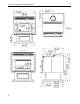
HT-2000 Installation and Operation Manual 7 Clearances to Combustible Material The clearances shown in this section have been determined by test according to procedures set out in safety standards ULC S627 (Canada) and UL1482 (U.S.A.). When the stove is installed so that its surfaces are at or beyond the minimum clearances specified, combustible surfaces will not overheat under normal and even abnormal operating conditions.
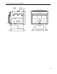
HT-2000 Installation and Operation Manual Clearances to combustible materials and floor protection 31
HT-2000 Installation and Operation Manual 7.3 Floor protector Your stove has been conceived to prevent the floor from overheating. However, it must be placed on a noncombustible surface to protect the floor from hot embers that could fall from the stove while loading or cleaning. There are differences between floor protections in Canada and in the United States, as it is illustrated in the table below and on the figure Clearances to combustible materials and floor protection.
HT-2000 Installation and Operation Manual 7.4 Reducing Wall and Ceiling Clearances Safely It is often desirable to reduce the minimum installation clearances by placing the stove closer to walls so the installation takes up less floor space. You can safely reduce the minimum clearances by permanently installing a shield between the stove and combustible material. The rules for safe shields can be complicated, so read them carefully and follow them exactly.
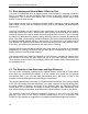
HT-2000 Installation and Operation Manual Clearances for shield construction 34
HT-2000 Installation and Operation Manual 7.4.2 Table of Clearance Reduction Percentages Clearances may be reduced by these percentages Sides and rear % Type of shield Top % (ceiling) Can/US A (%) USA min. Can/US A (%) USA min.
HT-2000 Installation and Operation Manual 8 The Venting System 8.1 General The venting system, made up of the chimney and the connecting pipe between the stove and the chimney, acts as the engine that drives your wood heating system. Even the best stove will not function safely and efficiently as intended if it is not connected to a suitable chimney. The heat in the flue gases that pass from the stove and chimney connector into the chimney is not waste heat.
HT-2000 Installation and Operation Manual To be suitable, a factory-built metal chimney must comply with UL 103 HT (U.S.A.) or ULC S629 (Canada). 8.2.1 Factory-built Metal Chimneys These are sometimes referred to as ‘high temp’ chimneys because they have the special characteristics to withstand the temperatures that can be created by wood burning stoves. Factory-built chimneys are tested as a system with all the necessary components for installation.
HT-2000 Installation and Operation Manual 8.2.2 Masonry Chimneys The stove may also be connected to a masonry chimney, provided the chimney complies with the construction rules found in the building code enforced locally. The chimney must have either a clay liner or a suitably listed stainless steel liner. If the masonry chimney has a square or rectangular liner that is larger in cross sectional area than a round 6” flue, it should be relined with a suitably listed 6” stainless steel liner.
HT-2000 Installation and Operation Manual 8.4 The Relationship Between the Chimney and the House Because the venting system is the engine that drives the wood heating system, it must have the right characteristics. The signs of bad system design are cold backdrafting when there is no fire in the stove, slow kindling of new fires, and smoke roll-out when the door is opened for loading. There are two guidelines to follow.
HT-2000 Installation and Operation Manual 8.4.2 Why the chimney should penetrate the highest heated space When it is cold outside, the warm air in the house is buoyant so it tends to rise. This tendency of warm air to rise creates a slight pressure difference in the house. Called ‘stack effect’, it produces a slightly negative pressure low in the house (relative to outside) and a slightly positive pressure zone high in the house.
HT-2000 Installation and Operation Manual Some jurisdictions in the United States require that wood stoves have a supply of combustion air from outdoors. If you do install an air supply through the wall of the house, be aware that its pressure can be affected during windy weather. If you notice changes in wood stove performance in windy weather, and in particular if smoke puffs from the stove, you should disconnect the outdoor air duct from the stove and remove the duct.
HT-2000 Installation and Operation Manual 8.6.1 Installation of Single Wall Chimney Connector The chimney connector assembly has been called ‘the weak link’ in the safety of wood heating systems because failure to install the connector properly (which has been common in the past) can result in house fires. The best flue pipe assembly is one that rises straight up from the stove to the base of the chimney with no elbows.
HT-2000 Installation and Operation Manual The rules below are based on those found in the CSA B365 installation code. Please carefully follow these installation instruction rules, or those enforced where you live. • • • • • • • • • • • • • • • • Maximum overall length of straight pipe: 3 m (10 ft.) including elbows. Minimum clearance from combustible material: 450 mm (18 in.). The minimum clearance may be reduced by 50 percent to 225 mm (9 in.
HT-2000 Installation and Operation Manual Appendix 1: Installing the Pedestal The pedestal kit must be assembled to the firebox before positioning the stove. See installation instructions below: 1- Slide the pedestal surrounding (A) toward the back of the stove base and join it to the pedestal back surrounding (B). 2- Secure both parts together using a Phillips screwdriver and 2 screws (C).
HT-2000 Installation and Operation Manual Appendix 2: Installing Trims Your freestanding Drolet wood stove is equipped with decorative u-shaped trims. See installation instructions below: 1- Using a Phillips screwdriver, install decorative upper trims (A) & (B) by fastening screws (C) on both side of each trim. 2- Using a Phillips screwdriver, secure the primary air control knob (D) with 2 screws (E).
HT-2000 Installation and Operation Manual 3- Press the ashtray trim (F) on the upper edge of ashtray lip.
HT-2000 Installation and Operation Manual Appendix 3: Installation and Use of Optional Air Circulation Fan (AC02050), and Thermodiscs (AC02055 and AC05530) An optional fan can be installed on the back of the stove to increase the flow of air past heat exchange surfaces and to help circulate warm air in the room. When used regularly, the fan can provide a small increase in efficiency, up to 2 percent.
HT-2000 Installation and Operation Manual When using the optional fan, allow the stove to reach operating temperature (approximately one hour), before turning it on. The increased airflow from the fan cools the firebox and could affect the start-up combustion efficiency if the fan is turned on too early. You can also install a thermodisc to enable the blower to start or stop automatically when the stove is hot or too cold.
HT-2000 Installation and Operation Manual Appendix 4: Installation of Secondary Air Tubes 1-Starting with the rear tube, lean and insert the right end of the secondary air tube into the rear right channel hole. Then lift and insert the left end of the tube into the rear left channel. 2- Align the last hole of the tube in the left air channel spigot hole. Insert a cotter pin in order to maintain the tube in place. 3- Fold-up the cotter pin end to lock the tube.
HT-2000 Installation and Operation Manual Appendix 5: Baffle Installation 1- Remove the front secondary air tube (A) and its cotter pin (B) and the three first bricks (C) on the right side of the combustion chamber. 2- Pile up one insulation blanket (E) and an insulation weight (F) upon one baffle board (D). Insert them into the combustion chamber and pass them over the air channels. Push them to the back of the combustion chamber, making sure the baffle sits well on both air channels.
HT-2000 Installation and Operation Manual Note that secondary air tubes can be replaced without removing the baffle board. Important Notes: The air tubes are identified for placement as follows: Model Type of tube HT-2000 Front ► 28 holes of 0.203" Middle► 28 holes of 0.172’’ Rear ► 28 holes of 0.
HT-2000 Installation and Operation Manual Appendix 6: Exploded Diagram and Parts List 52
HT-2000 Installation and Operation Manual IMPORTANT: THIS IS DATED INFORMATION. When requesting service or replacement parts for your stove, please provide the model number and the serial number. We reserve the right to change parts due to technology upgrade or availability. Contact an authorized dealer to obtain any of these parts. Never use substitute materials. Use of non-approved parts can result in poor performance and safety hazards.
HT-2000 Installation and Operation Manual # Item Description Qty 33 30075 BRASS METAL SCREW #6 X 1/2" QUADREX 4 33 30142 NICKEL METAL SCREW #6 X 1/2" QUADREX 4 34 PL07727-01 GOLD PLATED AIR OUTLET DECORATIVE GRILL 1 34 PL07729 AIR OUTLET DECORATIVE GRILL BRUSHED NICKEL 1 35 SE02000-02 ASH DUMP COVER 1 36 PL36049 4 1/2" X 4 1/2'' X 1 1/4'' REFRACTORY BRICK 1 37 29010 4 1/2" X 9" X 1.
HT-2000 Installation and Operation Manual DROLET LIMITED LIFETIME WARRANTY The warranty of the manufacturer extends only to the original consumer purchaser and is not transferable. This warranty covers brand new products only, which have not been altered, modified nor repaired since shipment from factory. Proof of purchase (dated bill of sale), model name and serial number must be supplied when making any warranty claim to your DROLET dealer. This warranty applies to normal residential use only.