PYROPAK E.P.A. WOOD STOVE MANUAL US ENVIRONMENTAL PROTECTION AGENCY PHASE II CERTIFIED WOOD STOVE Verified and/or tested following ULC S627 and UL 1482 Standards by: Manufactured by: STOVE BUILDER INTERNATIONAL INC. 250, de Copenhague, Saint-Augustin-de-Desmaures (Québec) G3A 2H3 Tel: ( 418 ) 878-3040 Fax: ( 418 ) 878-3001 www.drolet.ca This manual is available for free download on the manufacturer’s web site. It is a copyrighted document. Re-sale is strictly prohibited.
INTRODUCTION Stove Builder International, one of the most important wood stove and fireplace manufacturers in North America, congratulates you on your purchase and wishes to help you get maximum satisfaction from your wood stove. In the pages that follow, we will give you advice on wood heating and controlled combustion as well as technical specifications regarding installation, operation and maintenance of the model you have chosen.
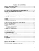
TABLE OF CONTENTS SECTION 1.0 - INSTALLATION ......................................................................... 4 1.1 GENERAL INSTALLATION................................................................................................. 4 1.2 POSITIONING THE STOVE ................................................................................................. 4 1.3 CLEARANCES TO COMBUSTIBLES AND FLOOR PROTECTOR ............................. 5 SECTION 2.0 CHIMNEY (FLUE SYSTEM) .......................
SECTION 1.0 - INSTALLATION When installed and operated as described in these instructions, the E.P.A Drolet Pyropak wood stove is suitable for use as a freestanding wood stove in residential installations. The E.P.A Drolet Pyropak wood stove is not intended for installation in a bedroom or a mobile home. In Canada, the CSA B365 Installation Code for Solid Fuel Burning Appliances and Equipment and the CSA C22.1 Canadian National Electrical Code are to be followed in the absence of local code requirements.
1.3 CLEARANCES TO COMBUSTIBLES AND FLOOR PROTECTOR To install your appliance correctly, it is extremely important to respect all clearances to any combustibles as indicated on your stove’s certification label. Clearances to combustible materials (see figure 1.
FIGURE 1.
Floor protector If the stove is to be installed on top of a combustible floor, it must be guarded by a non combustible material as shown on figure 1.3 (see the dotted line area). FLOOR PROTECTOR* G H I J M N CANADA 8" (203 mm) – Note 1 8’’ (203 mm) 18" (457 mm) From door opening N/A (USA only) 8" (203 mm) N/A (USA only) USA N/A (Canada only) N/A (Canada only) 16" (406 mm) From door opening 8" (203 mm) N/A (Canada only) Note 2 *Steel with a minimum thickness of 0.015’’ (0.
TYPE OF PROTECTION Reducing Clearances With Shielding Sides and Rear/Back Top Sheet metal, a minimum of 0,024" (0,61mm) spaced out at least 1" (25mm) by non-combustible spacers (see graphic 2). 67% 50% Ceramic tiles, or an equivalent non-combustible material on fire-proof supports spaced out at least 1" (25 mm) by noncombustible spacers (see graphic 3).
Graphic 1 A- Minimum clearance required between the appliance and an unshielded combustible ceiling. B- 20 in. (500 mm) minimum; C- 1 in. (25 mm) minimum; D- Between 1 in. and 3 in. (25 mm and 75 mm); E- 3 in.(75 mm) minimum; F- 18 in. (457 mm) minimum. 1- Shielding; 2- Non-combustible spacers; 3- Ceiling protector; 4- Combustible wall; 5- Ceiling; 6- Appliance (side view); 7- Appliance (top view). Graphic 2 A- 1 in.(25 mm) minimum; 1- Combustible wall; 2- Non-combustible spacers; 3- 0.024’’ (0.
Graphic 4 A- 1 in. (25 mm) minimum; 1- Combustible wall; 2- Non-combustible spacer; 3- 0.024’’ (0.61 mm) thick sheet metal; 4- Non-combustible support; 5- Ceramic tile or non-combustible material. Graphic 5 A- 1 in. (25 mm) minimum; 1- Combustible wall; 2- Non-combustible spacers; 3- Brick. Graphique 6 A- 1 in. (25 mm) minimum; 1- Combustible wall; 2- Non-combustible spacers; 3- 0.024’’ (0.61 mm) thick sheet metal; 4- Brick. WARNING: do not install in a sleeping room.
SECTION 2.0 CHIMNEY (FLUE SYSTEM) 2.1 DEFINITIONS For clarity, the following definitions should be used with respect to these instructions: A chimney system consists of a connector off the top of the stove, and a chimney, which attaches to the connector and terminates outside the house. A chimney can be a masonry chimney (of masonry construction with an inside liner), or a factory built chimney.
codes. In Canada the CSA B365 and the CSA C22.1 installation codes are to be followed. In the USA the ANSI NFPA 70 and ANSI NFPA 211 installation codes are to be followed. If you are using a masonry chimney, it is important that it be built in compliance with the specifications of the Building Code. It must be lined with fire clay bricks, or clay tiles, sealed together with fire cement, or have a listed solid fuel burning stainless steel liner. Round chimneys are the most efficient.
FIGURE 2.2 Minimum Height of the Chimney 2.2.1 Step by step installation of your factory-built chimney The way to install your chimney may vary from one chimney manufacturer to another. The instructions contained in this manual are based on the recommendations of chimney manufacturers whose products are sold at many North American retailers of wood stoves and related heating accessories.
FIGURE 2.2.
1- Start by positioning your stove where you would like it to go, taking into account the minimum clearances to combustible material. You will then be able to determine where the chimney will pass through the wall. You will probably have to adjust the stove position slightly to ensure that your chimney will run between the studs. You can use a stud finder to locate the studs.
4- Then, from outside the building, slide a short chimney length (attached to the tee) through the wall thimble. The chimney must extend at least 3 inches into the living space where it attaches to the stove pipe. 5- You can now install the wall support. Simply slide the wall support up to the tee, ensuring that the adapter on the support engages with the female coupler on the bottom of the tee. When the wall support is level and properly positioned, you can use lag bolts to secure it into the wall studs.
7- Authorities require that the chimney extend not less than 3 feet above the highest point where it passes through the roof of a building and not less than 2 feet above any portion of the building within 10 feet. If the chimney extends more than 5 feet above the roof deck, roof guys with telescoping legs and draw bands are required. 8- Finally, twist on your rain cap and you can head back inside. 9- You are now ready to connect your chimney to your stove.
Ceiling support system If your chimney must rise inside the house and go through the ceiling, you need to connect it to your stove at the ceiling level.
FIGURE 2.2.1 (B) Typical Installation Through the Ceiling 1. Place your stove where you would like it located and use a plumb line to mark the ceiling directly above your stove flue. You will probably have to adjust this position slightly to ensure that your chimney will run between the joists. You can use a stud finder to locate the joists. You also need to take into account the minimum clearances to combustible materials.
4. Once the support is secure, you can begin to assemble the chimney by lowering the first section into the support. Make sure that the male coupler is pointing upwards, as indicated by the arrow on the chimney label. 5. Then, from beneath the support, insert the stove pipe adapter and twist-lock it into place. 6. Now, you can add additional chimney sections. Continue adding chimney lengths until a height of about 2 feet below the next ceiling level.
7. Once you have cut through your roof and framed the joists, it is time to work outdoors. Authorities require that the chimney extend not less than 3 feet above the highest point where it passes through the roof of a building and not less that 2 feet above any portion of the building within 10 feet. You will need to install a roof flashing. The roof flashing slides over your chimney pipe and goes under your shingles.
2.2.2 Typical installation through an existing masonry chimney You can also install your stove using your existing masonry chimney. To do so, follow the guidelines below. You may want to use a factory-built thimble, on construct your own brick thimble. If you are using a masonry chimney, it is important that it be built in compliance with the specifications of the Building Code in your region. It must normally be lined with fire clay bricks, metal or clay tiles sealed together with fire cement.
FIGURE 2.2.
FIGURE 2.2.
2.3 CHIMNEY CONNECTOR Your chimney connector (commonly called stove pipe) and chimney must have the same diameter as the stove’s exhaust outlet. The stove pipe must be made of aluminized or cold roll steel with a minimum 24-gauge thickness (0.021" or 0.53 mm). It is strictly forbidden to use galvanized steel.
FIGURE 2.
2.4 DRAFT Your E.P.A Drolet stove’s performance will be optimised if it is installed with a chimney (flue) system that provides an adequate draft. The draft is the force that moves air from the appliance up through the chimney and is predominantly affected by the height and diameter of the chimney, as well as the stack temperatures of the stove. If you test the draft using a pressure gauge, the reading should be between .05 - .07 inches of water column (w.c.) at a medium-high fire.
2.6 THE ADVANTAGE OF INSTALLING A BLOWER (FAN) A blower can be installed at the back of your E.P.A Drolet Pyropak stove. This option is necessary if you wish to redistribute into a room the heat trapped at the back of your stove. By forcing hot air toward the front, the blower enables you to extend the radiation and convection power of your stove. You can purchase this option through your E.P.A Drolet dealer. Make sure you specify the correct part number: AC02050.
SECTION 3.0 OPERATION Keep these instructions for future reference. WARNING: ANY MODIFICATION OF THE APPLIANCE THAT HAS NOT BEEN APPROVED IN WRITING BY THE TESTING AUTHORITY IS CONSIDERED AS BREACHING CSA B365 (CANADA), AND ANSI NFPA 211 (USA). NEVER MODIFY THE AIR INTAKE CONTROL. DO NOT USE FLAMMABLE LIQUIDS OR AEROSOLS TO START OR REKINDLE THE FIRE. DO NOT USE FLAMMABLE LIQUIDS OR AEROSOLS IN THE VICINITY OF THIS APPLIANCE WHEN IT IS OPERATING.
3.1 SAFETY INFORMATION These stoves are designed for safe operation WHEN BURNING WOOD ONLY. Altering or modifying the unit or installation without proper authorisation will void the certification, warranty, and safety listing, and may result in a safety hazard. For safety reasons, never leave the unit unattended with the door open or ajar.
Although the ceramic glass is extremely durable under any normal use, a few precautions are required. Do not attempt to push logs further into the fire by using the door, as the glass may break if any solid object heavily contacts it. Never operate the stove with the door open, or cracked slightly open, except briefly during the lighting operation, and during refuelling. Leaving the door open continuously could seriously overheat the chimney and adjacent combustibles.
Energy yield (millions of BTU/cord) Oak 29 Sugar Maple 28 Beech 26 High energy yield Yellow birch 25 Ash 24 Elm 23 Larch (Tamarack) 23 Red Maple 23 Douglas red fir 23 Medium energy yield Silver birch 22 Alder 18 Poplar 17 Hemlock 17 Spruce 17 Pine 17 Low energy yield Bass 16 Fir 13 Data provided by Energy, Mines and Resources – Canada Wood species TABLE 3.2 Energy yield for wood species 3.2.1 The use of manufactured logs There are numerous types of manufactured logs sold on the market.
3.2.2 Simple wood moisture test Add one large piece of wood to the top of an established fire. If it starts to burn on three sides within one minute, it is dry and seasoned and right for burning. If it turns black and starts to burn in about three minutes or more, it is damp. If it turns black and does not start burning until five minutes or more, it is green and wet. If it hisses at any time, the wood is soaked and will not burn until the excess of moisture is boiled away. 3.
down too soon will lower combustion efficiency and may cause the fire to die out. Over a period of time, it may also result in creosote build-up in the chimney (which could lead a chimney fire). CLOSED OPEN 3.5 MAINTAINING THE FIRE Once the wood has been consumed (or partially consumed) and you have obtained a good bed of embers, you should reload the unit. In order to do so, open the air control to its maximum for approximately 15 seconds prior to opening the stove door.
In order to achieve an optimum efficiency from your unit, we suggest that you operate it with the air control completely closed. Make sure that you have a good fire going and an adequate ember bed before you completely close the air control. Use a chimney thermometer if necessary. Closing the air control too soon will lower combustion efficiency and may cause the fire to die out. The addition of a blower (if not already included) is highly recommended to maximize your unit’s efficiency. 3.
SECTION 4.0 MAINTENANCE 4.1 CLEANING AND PAINTING YOUR STOVE Clean the stove frequently so that soot, ash, and creosote do not accumulate. Do not attempt to clean the stove when the unit is hot. Special care must be taken with gold plated surfaces in order to maintain the finish at its original brilliance. Do not use an abrasive cleaner which will scratch the paint or plated finish. Use only a soft and clean damp cloth.
4.3 GASKETING It is recommended that you change the door gasket (which makes your stove door air tight) once a year, in order to insure good control over the combustion, maximum efficiency and security. To change the door gasket, simply remove the damaged one. Carefully clean the gasket groove, apply a high temperature silicone sold for this purpose, and install the new gasket. Use only the genuine Drolet gasket. You may light up your stove again approximately 24 hours after having completed this operation.
SECTION 5.0 FEATURES 5.1 Pyropak Type of fuel Wood Test standard ULC S627 (CSA B366.2) and UL 1482 for residential. Recommended surface: 500 to 1000 sq. ft. Heating capacity* – BTU/hr., EPA test wood: 26,100 Heating capacity* – BTU/hr.
BRICK LAYOUT ITEM 1 2 3 4 PART # 29010 PL36055 29015 PL36027 DESCRIPTION 4 ½” X 9” BRICK 4 1/2'” X 9” BRICK (CUT) 4” X 9” BRICK 3" X 9" X 1 1/4'' BRICK QTY 12 2 2 2 39
DROLET LIMITED LIFETIME WARRANTY The warranty of the manufacturer extends only to the original consumer purchaser and is not transferable. This warranty covers brand new products only, which have not been altered, modified nor repaired since shipment from factory. Proof of purchase (dated bill of sale), model name and serial number must be supplied when making any warranty claim to your DROLET dealer. This warranty applies to normal residential use only.