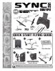
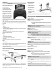
™ READ THESE INSTRUCTIONS BEFORE FLYING! Screwdriver Controller Sync 251 Drone 900 mAh Flight Battery USB Charger 4 AAA Batteries Spare Blades (2 black, 2 white) QUICK START FLYING GUIDE Turn on the controller. Connect charged battery. Close the door. Set on a flat surface. 1 2 Move the left stick up then down to arm the motors. Press and release to start motors. Press again to Auto Takeoff or Auto Land. FLY! WARNING: Product includes a lithium polymer (LiPo) battery.
LOCATION PRECAUTIONS NOTICE The Sync™ 251 drone uses optical flow technology to hold it in place. This works by taking repeated pictures of the ground and comparing the pixels from one picture to the next very fast. If it senses a change, the sensor will command the drone to adjust its position. While this technology is incredible, there are some things to watch for that can confuse the sensor: • Floors that are shiny and reflective may cause drifting as it tries to follow light reflections.
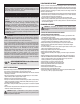
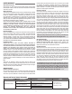
Auto Takeoff/Land CONTROLLER Motor Start Auto Takeoff/Land Video Button Throttle/ Rudder Stick Video Button Optics On/Off Throttle/ Rudder Stick On/Off Phone Holder Trim Flip HOW toPicture FLY Button Elevator Trim Phone Holder Flip B Picture Button Headless On/Off Rudder Trim ON/OFF D B Aileron/ Elevator Stick A C C Aileron/ Aileron Elevator TrimStick A D Headless On/Off Rudder Trim ON/OFF A Aileron Trim B B A Remove the screw on the battery compartment cover.
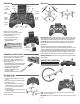
APP CONTROLS Low Voltage Alarm The LEDs on the arms will flash when the battery voltage is getting low. Land the drone as soon as possible and charge the battery. The battery must be charged before it is stored. ALWAYS disconnect the battery when it’s not in use! Headless Mode When you active this mode, the drone movements will be relative to the controller no matter which way the drone is pointing.
FLYING FPV Motor Replacement Your phone can be mounted in the holder on the controller or inserted in the VR headset (DIDZ1558) for a more immersive feel. 1. Remove the two screws from the foot. 2. Carefully remove the foot. The motor will unplug and come out with the foot. 3. Plug in the new motor and place it into the frame so the wires line up together. 4. Replace the foot carefully, so the wires get routed without getting pinched.
LIMITED WARRANTY to better answer your questions and service you in the event that you may need any assistance. For questions or assistance, please visit our website at www. horizonhobby.com, submit a Product Support Inquiry, or call the toll free telephone number referenced in the Warranty and Service Contact Information section to speak with a Product Support representative.
FCC INFORMATION installation. This equipment generates, uses and can radiate radio frequency energy and, if not installed and used in accordance with the instructions, may cause harmful interference to radio communications. However, there is no guarantee that interference will not occur in a particular installation.
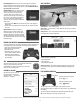
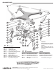
REPLACEMENT PARTS 1 2 1 11 6 6 4 5 5 12 3 8 6 13 5 10 7 4 4 3 3 5 2 7 14 3 13 3 Key No. 6 9 6 8 Part No. 3 4 Description DIDE1175 6 3x6mm Bearing (8) DIDE1176 5 Spur Gear set (4) DIDE1215 - TX Mobile Phone Holder DIDH0210 - MR210 Transmitter Sync 251 DIDH1101 11 3.